Oxford Technical Solutions Ltd. http://www.oxts.com
Page 22 of 42
Multipath effects on dual antenna systems
Dual antenna systems are very susceptible to the errors caused by multipath. Multipath is where the
signal from the satellite has a direct path and one or more reflected paths. Because the reflected paths
are not the same length as the direct path, the GNSS receiver cannot track the satellite signal as
accurately. This can be from buildings, trees, roof-bars, etc.
The dual antenna system in the xNAV works by comparing the carrier-phase measurements at the two
antennas. This tells the system the relative distance between the two antennas and which way they are
pointing (the heading). For the heading to be accurate the GNSS receivers must measure the relative
position to about 3 mm. The level of accuracy can only be achieved if there is little or no multipath.
In an ideal environment, with no surrounding buildings, trees, road signs or other reflective surfaces,
the only multipath received is from the vehicle’s roof. The antennas supplied with the xNAV are
designed to minimise multipath from
the vehicle’s roof when the roof is made of metal. For use on non-
metallic roofs a different type of antenna is required.
If you are using the INS in GNSS conditions where multipath effects are prevalent (lots of objects,
particularly buildings around) then it is worth using higher-end antennas that have a greater signal
filtering capability.
Antenna placement and orientation
For optimal performance it is essential for the GNSS antenna(s) to be mounted where they have a clear,
uninterrupted view of the sky and on a suitable ground plane, such as the roof of a vehicle. For good
multipath rejection the antennas must be mounted on a metal surface using the magnetic mounts
provided; no additional gap may be used.
The antennas cannot be mounted on non-conducting materials or near the edges of conducting
materials. If the antennas are to be mounted with no conductor below them then different antennas
must be used. It is recommended to mount the antennas at least 30 cm from any edge where possible.
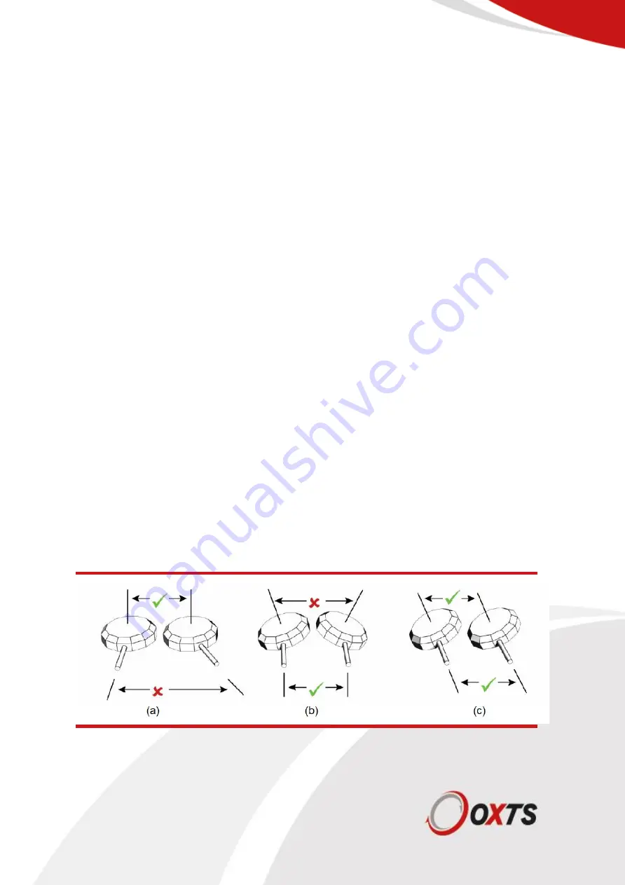
For dual antenna systems, the secondary antenna should be mounted in the same orientation as the
primary antenna, as shown in Figure 9. The antenna baseline should also be aligned with one of the
vehicle axes where possible, either inline or
perpendicular to the vehicle’s forward axis. In the default
configuration the primary antenna should be at the front of the vehicle and the secondary antenna
should be at the rear and they should be as far apart as possible.
Figure 9: Dual antenna orientations
a) The bases of the antennas are parallel, but the cables exit in different directions.
Summary of Contents for xNAV650
Page 1: ...xNAV650 Hardware Manual 20 Years Navigation Experience in one small INS ...
Page 38: ...Oxford Technical Solutions Ltd http www oxts com Page 38 of 42 Appendix 2 Drawings ...
Page 39: ...Oxford Technical Solutions Ltd http www oxts com Page 39 of 42 ...
Page 40: ...Oxford Technical Solutions Ltd http www oxts com Page 40 of 42 Revision history ...


