Oxford Technical Solutions Ltd. http://www.oxts.com
Page 16 of 42
PPS
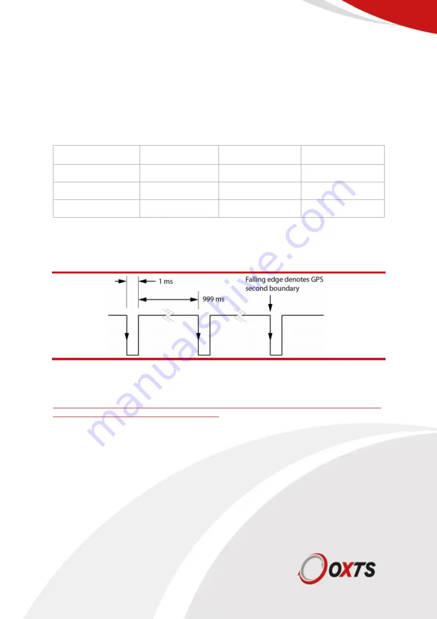
The PPS output is a pulse generated by the GNSS receiver. The output is active even when the GNSS
receiver has no valid position measurement. The falling edge of the pulse is the exact transition from
one second to the next in GPS time. The pulse is low for 1 ms, then high for 999 ms and repeats every
second. The output is a low-voltage CMOS output, with 0.8 V or less representing a low and 2.4 V or
more representing a high. No more than 10 mA should be drawn from this output.
Table 8: PPS electrical specifications
PPS
Typical
Min
Max
Output Voltage High (V)
3.3
2
3.3
Output Voltage Low (V)
0
-
0.8
Output Current (mA)
-
-
2
The signal is configurable to the rising or falling edge. For details, please refer to the support article for
NAVconfig or check the hardware section of this manual.
Figure 6: PPS waveform
Serial
The serial interface uses a standard 5V logic RS232. The exact transceiver used is the
SN65C3221EPWR. For full details you can read the datasheet from Texas Instruments
Summary of Contents for xNAV650
Page 1: ...xNAV650 Hardware Manual 20 Years Navigation Experience in one small INS ...
Page 38: ...Oxford Technical Solutions Ltd http www oxts com Page 38 of 42 Appendix 2 Drawings ...
Page 39: ...Oxford Technical Solutions Ltd http www oxts com Page 39 of 42 ...
Page 40: ...Oxford Technical Solutions Ltd http www oxts com Page 40 of 42 Revision history ...


