background image

Over

view

OOve

r-

view

Connecting the devices

To use the devices together you need to send NMEA messages over serial and PPS messages from the INS to the LiDAR. 

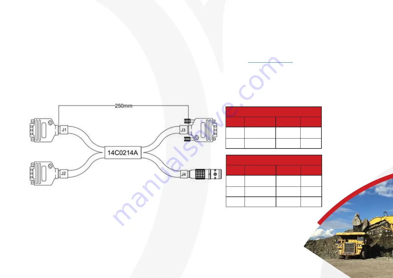
This can be done simply using a Z+F adapter cable and the right connectors on the INS user cable. If you wish to use 

your OxTS INS with the Z+F LiDAR you can purchase the adapter cable by emailing 

sales@oxts.com


and quoting the part 

number 14C0214A.
If your user cable does not have the right connectors, modify the cable so that it has two 9-Way connectors correctly 

wired for serial and for digital I/O. These are connected directly to the adapter cable which connects straight into the 

LiDAR. 

Diagram of the Z+F Profiler adapter cable

Radio

Pin

Function Colour Conn

2

RS232 RX

Blue

J1-2

5

Ground

Black

J1-5

Z+F Profiler

Pin

Function Colour Conn

1

RS232 TX Yellow

J1-3

3+10

Ground

Black

J2-6

9

1PPS

Green

J2-1

Summary of Contents for Z+F LiDAR 9012

Page 1: ...Z F LiDAR Hardware integration guide ...

Page 2: ...iDAR data The xNAV650 and Survey INS are an ideal companion to the Z F 9012 Profiler They incorporate survey grade RTK capable dual GNSS receivers and high grade MEMS inertial sensors for maximum position accuracy and precise heading and orientation measurements Requirements Overview In order to integrate the xNAV650 or Survey with the Z F 9012 Profiler the following equipment is needed OxTS INS O...

Page 3: ...by emailing sales oxts com and quoting the part number 14C0214A If your user cable does not have the right connectors modify the cable so that it has two 9 Way connectors correctly wired for serial and for digital I O These are connected directly to the adapter cable which connects straight into the LiDAR Diagram of the Z F Profiler adapter cable Radio Pin Function Colour Conn 2 RS232 RX Blue J1 2...

Page 4: ... 9 Way male D type connectors in the following way J1 Pin Wire Colour Signal Terminate to 3 Red RS232 RX J4 2 4 ORG RS232 TX J4 3 11 W BLK Signal Ground J5 6 9 J4 5 12 W BRN PPS J5 1 13 W RED I O Signal 2 J5 2 9 GRY I O Signal 1 J5 3 Pin Function Conn 2 Red J1 3 3 ORG J1 4 5 W BLK J1 11 Pin Function Conn 1 1PPS J1 12 2 I O 1 J1 13 3 I O 2 J1 9 6 9 Digital Ground J1 11 J4 RS232 J5 Digital I O ...

Page 5: ... You will need an ethernet connection to the INS device All the settings relevant for this integration are found in the Interfaces section as shown below The Z F 9012 Profiler requires a once per second GPZDA NMEA message to timestamp the laser firing The NMEA messages are configured on the serial output On the Serial 1 Output tab configure the serial to output NMEA packets at a baud rate of 9600 ...

Page 6: ...put triggers Collecting Data All OxTS INS will automatically record raw data onto their onboard storage You can FTP to the IP address of your system at the end of the data collection either via Windows FTP an FTP client or through NAVsolve Z F data will be recorded in Z F s Laser Control software Be sure to check in the Z F software that the PPS and NMEA are being received successfully before comp...

Page 7: ...lipsoidal Roll Decimal degree Pitch Decimal degree Heading Decimal degree The actual georeferencing will take place using your OxTS output file and the Z F 9012 Profiler raw data To do this the Z F Syncat is needed For more information follow the link and contact Z F if more help is needed This can also be done easily in NAVgraph by right clicking the graph and exporting as a CSV file after you ha...

Page 8: ...Example Data The data to produce the images below was collected using an OxTS xNAV550 INS and a Z F 9012 Profiler LiDAR sensor ...

Page 9: ...Example Data cont Similar to the page opposite These pointclouds were created using the OxTS xNAV550 INS and a Z F 9012 Profiler LiDAR sensor ...

Page 10: ...Need further assistance Visit the support website support oxts com Get in touch if you can t find what you need support oxts com Support 44 0 1869 814251 Sales 44 0 1869 814253 ...

Reviews: