Rev.0 LEPTON
Service
manual
OXYGEN S.p.A.
16
MOUNTING THE DRIVE
•
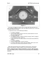
Place the drive near the motor;
•
Connect the signal cable from the drive in the appropriate connector on the
top of the motor flange (4 – Figure5);
•
Connect the ground cable (Yellow / Green) from DRIVE to the motor casing
(2 - Figure 5);
•
Attach the drive to the frame brackets carefully after having placed all the
wires from the drive inside the frame itself, without blocking the screws;
•
Connect the 2 signal cables with the electrical system into the front shield
(10/11 – Figure 5), taking care that this cables should be insert and block to
the frame ( under the footboard, like originally ). Blocking the 2 cables with
self-blocking band;
•
Connect the wires attached directly to the DRIVE;
o
RED wire (10 mm
2
section) from terminal 87 of the switch (12 – Figure
5);
o
BLUE wire drive wire from the yellow wire of the scooter’s electrical
system (16 – Figure 5);
•
If it’s present, cut the fastening clamp to the BLACK wire from the DRIVE (8
– Figura 5) and remove 10 mm of the plastic coverage. Connect the wire with
the screw contact (8/a – Figure 5/a) coming to the NEGATIVE pole o fthe
battery pack (8 – Figura 5/a);
•
Fixing completely the DRIVE to the frame brackets (0 – Figure 5/a), then
fixing the cooling fun (18 – Figure 5/a) with the correct gradient;
•
Connect with the Z10-1 clamps the motor power cables(Black / Red / Green)
to the cable coming out of the DRIVE (Black / Brown / Blue) (1 - Figure 5);
o
RED wire from DRIVE with RED motor wire
o
BLACK wire from DRIVE with BLACK motor wire
o
BLUE wire from DRIVE with GREEN motor wire
•
Cover the Z10-1 clamps with heat-restringent covers employ a phon in order
to covering completely the connectors. In absence of the thermal shealth,
employ a insulating adhesive. Then grouping the 3 cables and block with
self-blocking bands to the near frame bracket, tacking care that this clamping
will not block the normal oscillation of the rear fork , and the rear fork will not
pull the cables from the motor;
•
Connect the POSITIVE pole (7 – Figure 5/a) and the temperature sensor (22
– Figure 5/a) on the POSITIVE pole of the battery pack, take care that the
temperature sensor will not be damaged ( to know the correct fixing power to
practice on the screw contacts of the Ni-Zn batteries, read carefully the


