background image

Rev.0 LEPTON 

Service 

manual 


OXYGEN S.p.A. 


50

4.8 5.8 8.8 10.9 

12.9 

d x p 

mm 

Sr 

mm

²


kN 

M


N·m 

F


KN 

M


N·m 

kN


N·m


kN


N·m


kN


N·m


27x2  496 131 615 162 760 225 1200

363 1700 425 1990

30x3.5 561 144 772 178 955 280 1500

399 2130 467 2500

30x2  621 165 859 204 1060

321 1670

457 2370 535 2780

Summary of Contents for LEPTON

Page 1: ...Rev 0 CE DOT Service manual Freedom By Choice LEPTON LEPTON e...

Page 2: ...ATTERIES VERSION 14 REMOVING THE DRIVE 14 MOUNTING THE DRIVE 16 BATTERIES LEAD SEALED VERSION 18 MOUNTING REMOVING THE BATTERIES 18 BATTERIES NI ZN VERSION 20 MOUNTING REMOVING THE BATTERIES 20 BATTER...

Page 3: ...YGEN S p A 3 LIST AND PROCEDURES OF CONTROLS 41 FUSES 44 FUSES ON LINE 230 VAC 45 FUSE INSERTED TO THE BATTERIES POSITIVE POLE 46 SERVICES FUSE AND IGNITION FUSE 47 FORELOADS P AND CLAMPING TORQUES M...

Page 4: ...Maintenace Manual and to the Warranty Manual So before reading this document it is necessary to read the information containerd in the Use and Maintenance Manual and in the Warranty Manual In this man...

Page 5: ...r Lepton Pb the battery voltage must be higher than 50 Volt If it is between 46 Volt and 50 Volt make a complete recharge as soon as you can if lower than 46 Volt contact OXYGEN at once For Lepton Ni...

Page 6: ...ntion is given to the quality of its components and to their assembling Anyway during packaging storaging transport moving and receiving of the vehicle damages to the components might occur INSTRUCTIO...

Page 7: ...h 4 screws Figure 1 The entire motor is connected to the frame by means of a special splinter bar 3 Figure 1 with two screws 4 Figure 1 NOTE The electric motor cannot be separated from the transmissio...

Page 8: ...h the corresponding connectors from the hole in the motor flange 4 Figure 5 Unscrew all the screw 3 in Figure 4 to allow the rotation of the mudguard in order to facilitate the dismantlement of the re...

Page 9: ...top of the motor frame 4 Figure 5 Connect the ground cable yellow green 2 Figure 5 Connect with the Z10 1 clamps the motor power cables Black Red Green to the cable coming out of the DRIVE Black Brown...

Page 10: ...ON Service manual OXYGEN S p A 10 Mount the helmet storage compartment supply to connect the battery recharger plug 17 Figure 5 and the connector of the rear light system 19 Figure 5 Functionality tes...

Page 11: ...Rev 0 LEPTON Service manual OXYGEN S p A 11 DRIVE BATTERY CHARGER LEAD SEALED BATTERIES VERSION Figure 5...

Page 12: ...ow Green from where it is attached to the motor casing 2 Figure 5 Remove the front shield unscrewing the 4 screws 9 Figure 5 Disconnect the 3 connectors from the electrical system 10 11 Figure 5 and c...

Page 13: ...ure 5 then fixing the cooling fun 18 Figure 5 with the correct gradient Connect with the Z10 1 clamps the motor power cables Black Red Green to the cable coming out of the DRIVE Black Brown Blue 1 Fig...

Page 14: ...he battery pack disconnect the POSITIVE pole 7 Figura 5 a from the batteries NOTE there is a temperature sensor mounting to an aluminum bar connect with the POSITIVE pole 22 Figure 5 a Taking care to...

Page 15: ...unscrewing the 4 screws 9 Figure 5 a Disconnect the 3 connectors from the electrical system 10 11 Figure 5 a and cut the self blocking band These cables are connected directly with the DRIVE Pull them...

Page 16: ...Connect the wire with the screw contact 8 a Figure 5 a coming to the NEGATIVE pole o fthe battery pack 8 Figura 5 a Fixing completely the DRIVE to the frame brackets 0 Figure 5 a then fixing the cooli...

Page 17: ...ith the scooter Functionality test Group all the motor cables and the main cables with self blocking bands like under the interventions Mount the helmet storage compartment supply to connect the batte...

Page 18: ...numbered sequence Remove the case cover 2 Figure 7 from the scooter to access the batteries The case cover is attached in the front with a lock 3 Figure 7 and a notch in the back Press down on the fr...

Page 19: ...battery with a red sticker the cable with the blue caps to the pegs on the battery group identified on the battery with blue sticker the cables with the green caps to the pegs of the battery group id...

Page 20: ...e case cover is attached in the front with a lock 3 Figure 7 and a notch in the back Press down on the front of the rod that holds the battery 4 Figure 7 in place to disconnect it from the fastening c...

Page 21: ...7 holding the battery in place 5 Figure 7 3 Using the appropriately sized tool disconnect the NEGATIVE pole from the battery black cable with the lug on the left Figure 7 b 4 Using the same tool disc...

Page 22: ...s with each battery pack for instructions on o removing the battery terminal caps o the correct tightness of the screws for each cable for proper electrical contact and to maintain the integrity of th...

Page 23: ...erage consumption would be greater thus the remaining charge lower for example around 25 km The charge remaining would increase once again if the scooter returned to a level road On a descent average...

Page 24: ...ge to run out when it cannot be avoided Do not leave the batteries in an uncharged state for even a short period of time Only charge the batteries with the battery charger that came with the bicycle o...

Page 25: ...arge left in the batteries may not be able to determine with accuracy the actual charge number of residual kilometers remaining CAUTION When charging the batteries verify that the current and voltage...

Page 26: ...authorize only the LEPTON connected with this DRIVE identification code In order to make the scooter starting You have to insert the key correctely into the connector The connector is placed on the l...

Page 27: ...starting so that the message CODE will appear on the dashboard LCD 8 Figure 11 Let the scooter stay on this state at least for 30 seconds Now the DRIVE is initialized Turn OFF the LEPTON Take off the...

Page 28: ...istence value variations of the potentiometer This resistence value is read by the DRIVE that gives the required electric power to run with the scooter The potentiometer is inside the front shield Fig...

Page 29: ...urn a throttle at the maximum rotation point then check that the maximum position of the throttle coincides to the maximum position of the potentiometer braket Do the same test again with the LEPTON t...

Page 30: ...safety of the vehicle and the correct functioning of LEPTON S main components Wirings for auxiliary systems lights acoustic signal etc refer to the normal rules of intervention Control wiring it tran...

Page 31: ...e the exposed parts of the bicycle with petroleum jelly NOTE Grease on the battery terminal posts decreases contact between the batteries and the connection cable It also impedes the delivery of energ...

Page 32: ...aced NOTE Dispose of the batteries in an environmentally responsible manner CAUTION The battery is an energy source If that energy is released in an uncontrolled way for example through a short circui...

Page 33: ...g on it Do not wear rings bracelets wristwatches or metal buckles while working on batteries Do not run batteries in closed areas Do not disconnect the battery recharger before the battery has been co...

Page 34: ...pose a decrease of performance under the same conditions of use even of 50 between 30 C and 0 C To be precise the temperature of reference is that inside the battery The thermic exchange with the envi...

Page 35: ...and a short circuit can create dangerous situations With the hermetic batteries it is not possible to control the density of the electrolyte just because of how they are produced which is the traditi...

Page 36: ...dvisable to recharge it using the internal battery charger If this procedure is not respected irreversible damages might occur to the batteries WARNING Ni Zn LEPTON can recover its initial performance...

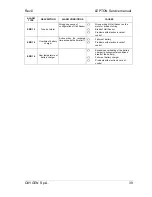
Page 37: ...ategory indicates temporary breakdowns or malfunctions that allow the rider to continue travelling even if the conditions are not optimal The letters All appear for 5 seconds every 20 seconds ERROR Th...

Page 38: ...e Break of temperature sensor Problems with electronic card of control ERR 5 Motor temperature second high and low level Default level value 140 C Default level low 25 C Intervention time 1 s Real val...

Page 39: ...ing Break of Hall Sensor Problems with electronic card of control ERR 14 Overtime of battery charger Active when the recharge time exceeds the time limit Failure of battery Problems with electronic ca...

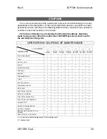
Page 40: ...ERATIONS n 0 Km 0 0 months n 1 Km 500 4 months n 2 Km 4000 12 months n 3 Km 8000 18 months n 4 Km 12000 24 months n 5 Km 16000 30 months n 6 Km 20000 36 months SHOCK ABSORBER C C C C C FORK C C C C C...

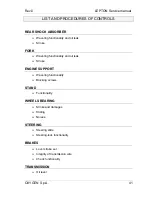
Page 41: ...k Stroke FORK Wavering functionality and oil leak Stroke ENGINE SUPPORT Wavering functionality Blocking screws STAND Functionality WHEELS BEARING Stroke and damages Sliding Noises STEERING Steering sl...

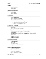
Page 42: ...ntacts Ni Zn model ELECTRICAL SYSTEM Start button Check potentiometer functionality Sprint mode button Indicators switch Indicator lights Indicator lamps Mode button Headlight switch Headlight light H...

Page 43: ...manual Warranty Check frame serial number if existing Check batteries serial number Check motor serial number Check Drive serial number Under the vehicle delivery Clean the vehicle Check keys functio...

Page 44: ...the vehicle and the batteries Before working on these devices pay attention to the following precautions BE SURE THAT WHEN REPLACING ANY ONE OF THE FUSES THE LEPTON IS OFF OR THAT THE RECHARGE PLUG IS...

Page 45: ...r recharge 20 Figure 5 They are two fuses 230V 6 3 A format 5X20 inserted inside the two cases Figure 12 you reach the fuses by lifting the saddle of the LEPTON These fuses work in case of short circu...

Page 46: ...HE BATTERIES POSITIVE POLE This fuse under the helmet holder is connected to the POSITIVE POLE of the series of batteries under the footrest tunnel of the LEPTON It is a belt fuse of 70 A Figure 13 an...

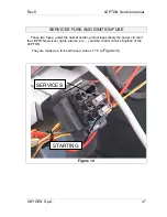
Page 47: ...ION FUSE These two fuses under the helmet holder protect respectively the power circuit of the LEPTON services lights alarms etc and the control circuit of ignition of the LEPTON They are made as a fo...

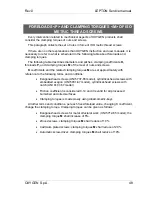
Page 48: ...the related clamping torques M are set approximately with reference to the following terms and conditions Exagonal head screws UNI 5737 65 model cylindrical head screws with embedded exagon UNI 5931 6...

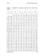
Page 49: ...3 27 50 40 73 47 86 10x1 25 61 2 15 8 28 19 5 35 30 53 43 76 51 91 12x1 75 84 3 21 3 46 26 56 40 86 59 127 69 148 12x1 25 92 1 23 8 50 29 62 45 95 66 139 77 163 14x2 115 29 73 36 90 55 137 80 201 94 2...

Page 50: ...5 8 8 8 10 9 12 9 d x p mm Sr mm F kN M N m F KN M N m F kN M N m F kN M N m F kN M N m 27x2 496 131 615 162 760 225 1200 363 1700 425 1990 30x3 5 561 144 772 178 955 280 1500 399 2130 467 2500 30x2...

Page 51: ...Rev 0 LEPTON Service manual OXYGEN S p A 51 OXYGEN S p A Via Ponticello 44 35129 Padova Tel 39 0 49 8282311 Fax 39 0 49 8079871 Sito internet www oxygenworld net E mail info oxygenworld net...

Reviews: