Rev.0 LEPTON
Service
manual
OXYGEN S.p.A.
9
Figure 2
Figure 3
MOUNTING THE ELECTRIC MOTOR
•
Attach the motor to the splinter bar with the appropriate screws (3 - Figure 1);
•
Attach the rear mudguard with only 2 screw (2 – Figure 4);
•
Attach the splinter bar and the motor to the frame with the 2 appropriate
screws (4 – Figura 1);
•
Attach the rear shock absorber to the motor;
•
Mount the jaw brakes, the ogive jaw and the ogive brake;
•
Connect the sheath of the rear brake wire;
•
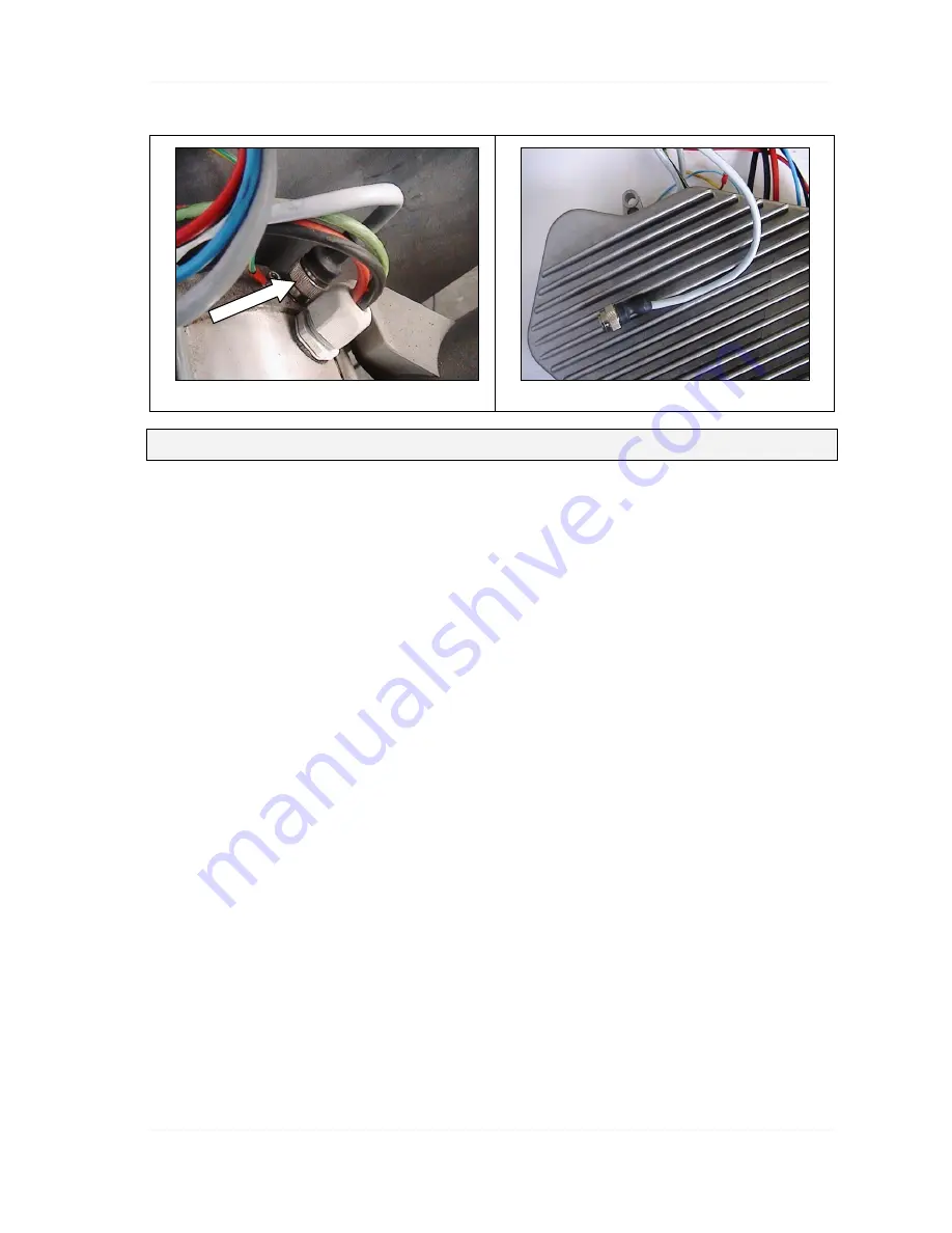
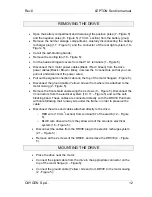
Connect the cable with the connector to the top of the motor frame(4 - Figure
5);
•
Connect the ground cable (yellow/green) (2 - Figure 5);
•
Connect with the Z10-1 clamps the motor power cables(Black / Red / Green)
to the cable coming out of the DRIVE (Black / Brown / Blue) (1 - Figure 5);
o
RED wire from DRIVE with RED motor wire
o
BLACK wire from DRIVE with BLACK motor wire
o
BLUE wire from DRIVE with GREEN motor wire
•
Cover the Z10-1 clamps with heat-restringent covers employ a phon in order
to covering completely the connectors. In absence of the thermal shealth,
employ a insulating adhesive;
•
Mount the rear wheel;
•
Fix the rear mudguard (3 – Figure 4);
•
Test the motor;
•
Group all the motor cables and the main cables with self blocking bands like
under the interventions;


