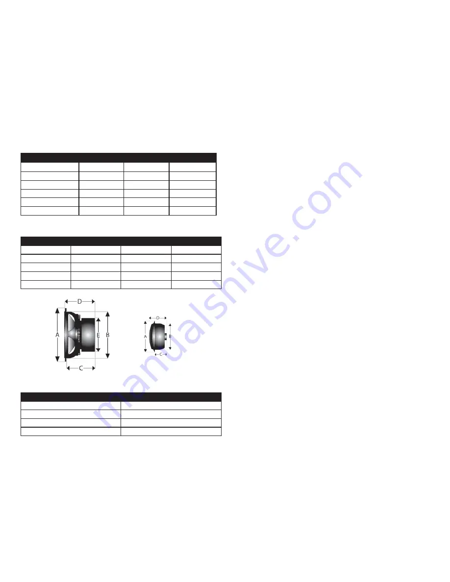
Matrix Component Specifi cations:
Model
ME OZ 180CS
ME OZ 130CS
ME OZ 100CS
Freq. Response:
36 Hz – 40 KHz
55 Hz – 40 KHz
65 Hz – 40 KHz
RMS PWR:
150 - 225 watts 130 - 200 watts
100 – 150 watts
Peak PWR:
300 - 450 watts
280 - 400 watts
220 – 330 watts
SPL @ 1w/1m
91 dB
92 dB
92 dB
Nominal Impedance:
4 Ω
4 Ω
4 Ω
Crossover point:
1800 Hz
1800 Hz
1800 Hz
Matrix Mid-bass Dimensions:
Model
ME OZ 180CS
ME OZ 130CS
ME OZ 100CS
A
6.50”
5.25”
4”
B
5.625”
4.875”
3.625”
C
3.0”
2.625”
2.125”
D
3.25”
2.875”
2.25
E
3.75”
3.75”
2.875”
Matrix Tweeter Dimentions:
Tweeter
A
2.3125”
B
2.0”
C
.75”
D
1.25”.
Mid bass Installation:
Determine the mounting location. Factory speaker locations are recommended
for ease of installation. When installing in the factory speaker locations, make
sure that there is enough depth to accommodate the replacement speaker.
If an alternate location is used, measurements should be carefully taken before
any cutting is done to insure that there is enough depth and to make sure that
the speaker will not interfere with any moving parts in the vehicle (i.e. window
gears/braces, hood/trunk cables, etc.). Once the mounting location is decided
upon, the grill-mounting ring can be used as a template to mark the hole and
screw locations. If the panel that the speaker is to be mounted to can be re-
moved, then it is recommended that the panel be removed before cutting the
speaker hole. Once the hole is cut to fi t the speaker, replace the panel. If there
is any metal obstructing the installation of the speaker, with top panel in place,
mark the metal that needs to be removed and then remove it with tin snips or
saw.
If new wiring is necessary, make sure to route the wires under factory moldings
to make the installation as clean as possible. The minimum gauge recommend-
ed is 16 gauge to avoid signal loss. In addition, make sure that the new wiring
is clear of any screw or clip holes so that it will not be pinched or shorted after
the factory panels and mounting screws are replaced.
Once the speaker opening is cut and the wires are run, the wires can be con-
nected to the speaker and the speaker can be mounted. The speed clips and
screws that come with the packaging can be used to mount the speaker. If
mounting the speaker in a factory location, then the factory screws should be
utilized.
TWEETER INSTALLATION 180CS/130CS/100CS
When using the fl ush mounting system it is important that you install the tweeter
assembly in the proper location for optimum results. Be sure to verify that there
is enough room for the tweeter housing and wiring behind your chosen location.
If the tweeter assembly is being mounted in the door be certain that the area is
clear of obstructions when the door is closed. It’s also recommended that you
verify that the wires can be safely run from the tweeter location to the crossover.
Once these few precautions have been taken, you are ready to proceed.
You will need to make a 2” diameter hole (outside measurement.) A 2” hole saw
makes for an easy clean precise fi t. Mark your location for the tweeter
Summary of Contents for ME OZ 180CS
Page 1: ......


