10
© Oz inventions
Version 1.8
Controls and sockets overview
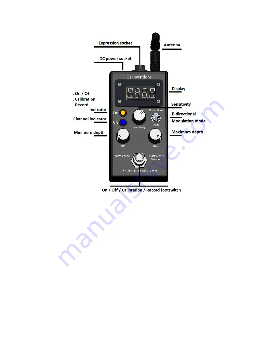
Figure 2 Top panel controls
Expression jack – Tip, Ring, Sleeve type 6.35mm (¼” )socket
Antenna – 2.4GHz vertical omni-directional 110mm antenna
Display – modulation mode; Sweep position; Menu text; mode indicators
Bidirectional switch –Positive modulation output, or Negative and positive modulation output
Mode switch – Tilt, rotation, Velocity, Force, Guitar-hand, Automatic, Playback
Minimum Depth – sets the minimum modulation position (heel down)
Maximum Depth - sets the maximum modulation position (toe down)
ON/OFF/calibration/record footswitch- Turns modulation on & off; Calibrates the the beginning and
ending modulation sweep points; Arms recording and stops recording.
Channel indicator – Three channels within the 2.4GHz spectrum; Identified as Red, Green and Blue
ON/OFF/calibration/record indicator – Yellow
Illuminated = Modulation ON; Extinguished = Modulation OFF; Fast flashing = calibrating; Brief slow
flashing = Record armed; Continuous slow flashing = Recording in progress.
Sensitivity – sets response time, stability, playback time and other parameters dependent on the
chosen modulation mode
DC power jack –2.1mm; 9 – 12V; 150mA; Negative centre


