background image

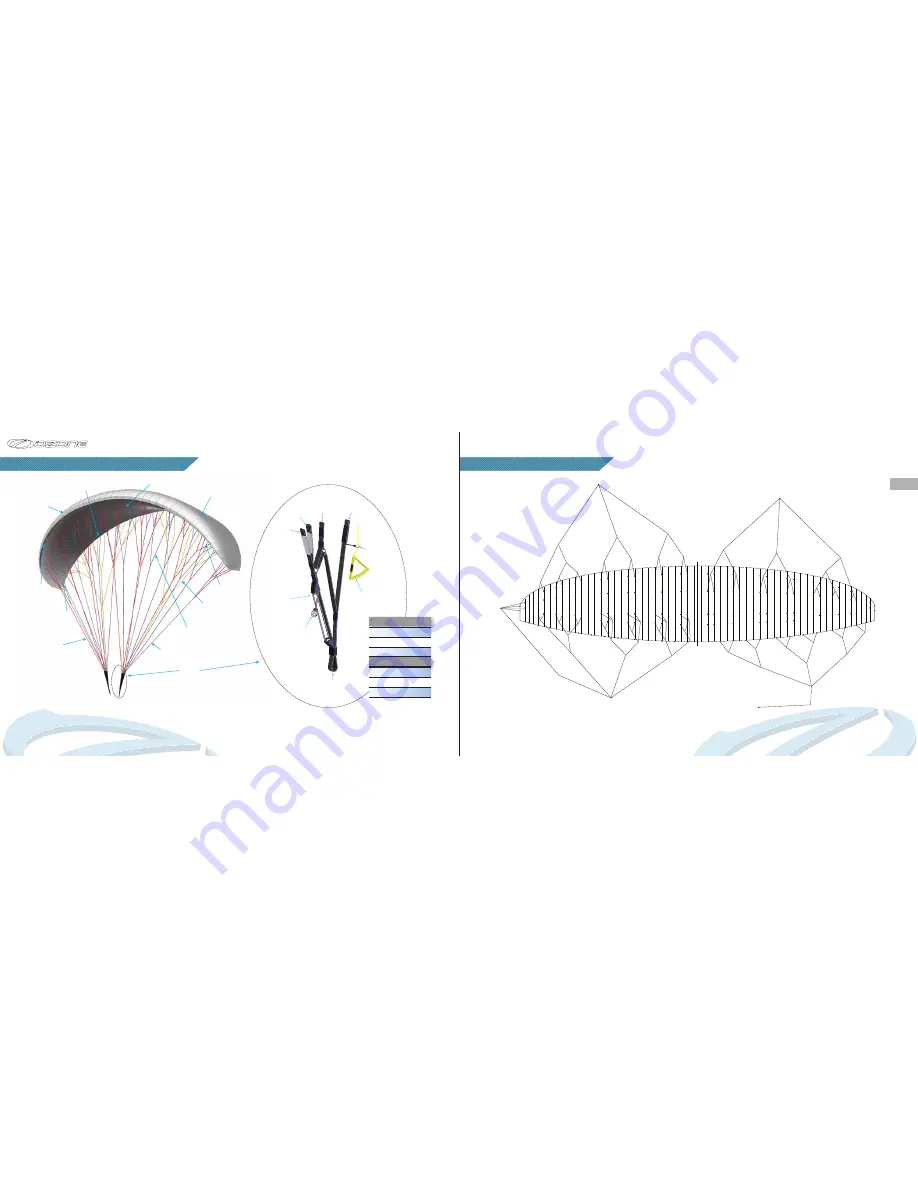
Rush 5 Rigging Diagram

A1

A2

A3

A4

A5

A6

A7

A8

A9

A10

A11

A12

A13

A14

A15

A16

B16

B15

B1

B2

B3

B4

B5

B6

B7

B8

B9 B10 B11 B12

B13 B14

C1

C2

C3

C4

C5

C6

C7

C8

C9

C10

C11

C12

C13

C14

D1

D2

D3

D4

D5

D6

D7

D8

CMU1

CMU2

CMU3

CMU4

CM5

CM6

CM1

CM2

CM3

CM4

DMU1

DMU2

DMU3

DMU4

CMU5

CMU6

CR1

CR2

CR3

CRU4

K1

K2

K3

K4

K5

K6

K7

K8

K9

K10

K11 K12

KMU1

KMU2

KMU3

KMU4

KMU5

KMU6

KML1

KML2

KML3

KRU1

KRL1

Brake handle

C riser

B riser

A riser

AM1

AM2

AM3

AM4

AM5

AM6

AMU1

AMU2

AR1

AR2

AR3

BM1

BM2

BM3

BM4

BM5

BM6

BMU1

BMU2

BR3

BR2

BR1

CRL4

TECHNICAL DRAWINGS

LINE DIAGRAM

EN

29

28

Leading 
Edge

Trailing 
Edge

Risers

Cell 
Openings

Riser 
Lines

Middle
Lines

Upper 
Lines

Stabilo Line

Brake 
Lines

Main Hangpoint

to Harness Carabiner

Riser

Baby A 

Riser 

B

Riser

Riser

Brummel Hook 

for Speed System

Brake 

Handle

Upper Surface

Lower Surface

Butt Hole


Accelerator 

Pulleys 

Pulley


Non Accelerated

 Accelerated  

Pulleys axis - axis

A

500mm

B

500mm

C

500mm

A

350mm

B

400mm

C

500mm

Individual and linked line lengths can be found online.

Summary of Contents for Rush 5

Page 1: ...Pilots Manual...

Page 2: ......

Page 3: ...development of the Ozone range As pilots we fully understand just how big an investment a new paraglider is We know that quality and value for money are essential considerations when choosing a new wi...

Page 4: ...rain snow strong wind turbulent weather conditions or clouds If you use good safe judgment you will enjoy many years of paragliding Remember PLEASURE is the reason for our sport Everyone at Ozone cont...

Page 5: ...s the Rush 5 stays at the top of its class Hundreds of hours test flying in real air and turbulent conditions have gone into the development of the Rush 5 ensuring the wing satisfies our own demanding...

Page 6: ...the angle of attack and makes the wing more prone to collapse therefore using the accelerator near the ground or in turbulent conditions should be avoided Accelerator System To set up the accelerator...

Page 7: ...s favourable whilst gently holding the A risers move forward positively your lines should become tight within one or two steps and the Rush 5 will immediately start to inflate You should maintain a co...

Page 8: ...re of your altitude and do not over react We strongly advise you to keep hold of your brakes at all times and to not fly in turbulent conditions IMPORTANT Always keep hold of your brakes Do not fly in...

Page 9: ...stall is for fast descents in emergency situations only sink rates of around 6 m s can be achieved It is however faster and safer to lose altitude with a spiral dive than a B stall To initiate the B s...

Page 10: ...ose pressure at the same time as releasing some or all of the accelerator you can also apply pressure to the C s this will help keep the nose open Be careful to use only small inputs with the C risers...

Page 11: ...at otherwise you risk spinning or deepening the spiral The aim is to empty the air out of the wing tip but without spinning Correctly done this action will clear the cravat quickly and is the most eff...

Page 12: ...ain your air speed at all times If your wing enters parachutal stall when wet immediately release the trimmers and accelerate the wing to regain airspeed Step 1 Lay mushroomed wing on the ground It is...

Page 13: ...om a mushroom or lift the wing off the ground when gathering the wing and grouping the leading edge IMPORTANT Do not fold the glider in the centre you will bend the plastics instead pack the wing with...

Page 14: ...e makes it easy to empty any sand leaves rocks mobile phones etc that may have accumulated in the wing It is recommended that you regularly CHECK your wing especially after a heavy period of use after...

Page 15: ...sic elements of the check up Porosity is measured with a porosity meter the time taken by a certain volume of air to go through a certain surface of the cloth The time in seconds is the result A measu...

Page 16: ...be one of them Launching is the time that you are most exposed to danger so practice it lots Some launch sites are small and difficult and conditions aren t always perfect If you re good at ground ha...

Page 17: ...C riser B riser A riser AM1 AM2 AM3 AM4 AM5 AM6 AMU1 AMU2 AR1 AR2 AR3 BM1 BM2 BM3 BM4 BM5 BM6 BMU1 BMU2 BR3 BR2 BR1 CRL4 TECHNICAL DRAWINGS LINE DIAGRAM EN 29 28 Leading Edge Trailing Edge Risers Cell...

Page 18: ...pper Surface Dominico DOKDO 30D MF Lower Surface Dominico DOKDO 30D MF Internal Ribs Dominico DOKDO 30D FM Leading Edge Reinforcement 2 5 1 8 1 4mm Plastic Main Line Set Riser Lines PPSL 200 120 PPSL...

Page 19: ...1258 Route de Grasse Le Bar sur Loup 06620 France...

Reviews: