CDV Construction Manual – Issue 3
Page 18
9
S
ET
-
UP
9.1
G
ENERAL
The CDV has a comprehensive range of programmable parameters which allow the CDV to be
used in a number of varied operating conditions.
To provide for easy and faster operation the Set-up menus are divided into three levels:
a.
QUICK – this level only includes the common main menus.
b.
MISC – this level is used to set the miscellaneous functions.
c.
FULL – all Set-up menus are available.
9.2
P
ROCEDURE
1.
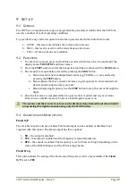
To enter Set-up mode, press and hold the encoder switch down for 2 seconds until the
display shows
CDV SETUP
and then release.
2.
Press the
STEP
button to select the Set-up level and then confirm with the
SCAN
button.
3.
The menus are sequentially accessed by pressing the
SCAN
button.
a.
Menu items that have multiple fixed values (e.g. YES/NO, +/-) are selected by
pressing the
STEP
button.
b.
Menu options that have numerical values (e.g. frequency) are incremented and
decremented using the rotary encoder.
c.
Menus displaying frequency use the
STEP
button to step the cursor through the
digits.
4.
Once the last menu is completed the Set-up procedure is exited and any new values
stored in non-volatile memory. These are loaded again at power on.
The menus and their current values can be displayed anytime without alteration by
progressing through the menus using only the SCAN button.
9.3
U
NDERSTANDING
M
ENU OPTIONS
Fixed O/P
The variable output is always enabled. The Fixed output can be enabled or disabled if not
required with this option. The Fixed output has three options:
1.
NO
– the output is disabled.
2.
YES
– the output is enabled and the frequency is manually entered.
3.
BFO
– the output is enabled. The frequency is set to IF low or IF high depending on the
state of the USB/LSB input and the VFO mixing scheme.
Fixed Freq
This option allows the setting of the fixed output frequency, and is only available if the
Fixed
O/P
is set to
YES
.
Summary of Contents for CDV
Page 1: ...CDV Construction Manual Issue 3 Page 1 CDV COMPACT DIGITAL VFO CONSTRUCTION MANUAL ...
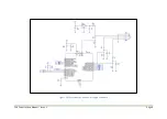
Page 8: ...CDV Construction Manual Issue 3 Page 8 Figure 1 Microcontroller and power supply schematic ...
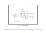
Page 9: ...CDV Construction Manual Issue 3 Page 9 Figure 2 Si5351A Clock generator schematic ...
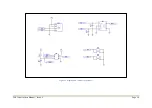
Page 10: ...CDV Construction Manual Issue 3 Page 10 Figure 3 Display and controls schematic ...
Page 30: ...CDV Construction Manual Issue 3 Page 30 Figure 11 Attenuator filter board fitted to the CDV ...

