CDV Construction Manual – Issue 3
Page 24
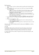
10.6
VFO
F
REQUENCY CALIBRATION
1.
Measure the actual CDV output frequency and compare this to the frequency displayed
on the OLED. Note the difference.
a.
If the CDV output frequency is less than the displayed frequency, the difference
needs to be subtracted in the Frequency Calibrate screen.
b.
If the CDV output frequency is greater than the displayed frequency, the
difference needs to be added in the Frequency Calibration screen.
2.
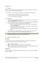
Enter Set-up and select either MISC or FULL. Step to the
CAL Freq
screen.
3.
Press the
STEP
button to toggle the sign indicator.
4.
Rotating the encoder will increase or decrease the difference value.
5.
Once set press the
SCAN
button to skip the remaining screens until Set-up is exited.
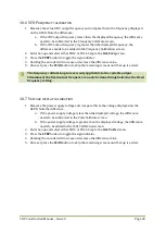
10.7
V
OLTAGE DISPLAY CALIBRATION
1.
Measure the power supply voltage and compare this to the voltage displayed on the
OLED. Note the difference.
a.
If the power supply voltage is less than the displayed voltage, the difference
needs to be subtracted in the Volts Calibrate screen.
b.
If the power supply voltage is greater than the displayed voltage, the difference
needs to be added in the Volts Calibration screen.
2.
Enter Set-up and select either MISC or FULL. Step to the
CAL Volts
screen.
3.
Press the
STEP
button to toggle the sign indicator.
4.
Rotating the encoder will increase or decrease the difference value.
5.
Once set press the
SCAN
button to skip the remaining screens until Set-up is exited.
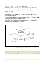
The frequency calibration process is only applicable to the variable output.
Trimming of the fixed output frequency can only be done through altering the Fixed
frequency setting.
Summary of Contents for CDV
Page 1: ...CDV Construction Manual Issue 3 Page 1 CDV COMPACT DIGITAL VFO CONSTRUCTION MANUAL ...
Page 8: ...CDV Construction Manual Issue 3 Page 8 Figure 1 Microcontroller and power supply schematic ...
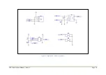
Page 9: ...CDV Construction Manual Issue 3 Page 9 Figure 2 Si5351A Clock generator schematic ...
Page 10: ...CDV Construction Manual Issue 3 Page 10 Figure 3 Display and controls schematic ...
Page 30: ...CDV Construction Manual Issue 3 Page 30 Figure 11 Attenuator filter board fitted to the CDV ...

