CDV Construction Manual – Issue 3
Page 26
12
O
PTIONAL
A
TTENUATOR
L
OW PASS
F
ILTER
B
OARD
The clock generator outputs square wave signals with an amplitude of around 2V pk-pk into 50
ohms. Some situations, however, may require a signal with either lower amplitude or reduced
harmonics, or both.
The optional add-on board contains a simple resistive attenuator and a 5 pole low pass filter
and can be applied to one or both outputs. It can be soldered directly to the rear of the CDV to
make a compact assembly or mounted externally and wired in-line.
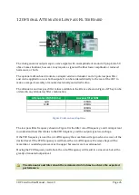
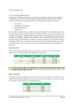
The attenuator and low-pass filter values available in the kits are shown in Figure 8. They can be
ordered in any attenuator/filter combination.
Attenuator dB (50 ohms)
Low pass filter MHz
6dB
10MHz
12dB
20MHz
30MHz
40MHz
Figure 8 Add-on board options
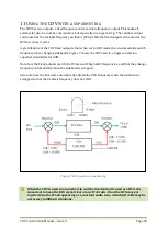
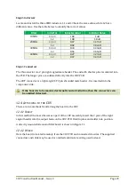
The low pass filter frequency shown in Figure 8 is the filter cut-off frequency, and it is important
to understand how this relates to the VFO frequency, and the output signal wave shape.
If the VFO frequency is near the cut-off frequency the waveform will approach a sine wave of the
desired level. If the VFO frequency is well below the cut-off frequency the wave shape will be
more like a rounded square wave as the upper harmonics are less attenuated.
Moving the VFO frequency well above the cut-off frequency will result in a sine wave but with a
greatly attenuated output level.
The attenuator and filter should be terminated in 50 ohms to achieve the expected
performance.
Summary of Contents for CDV
Page 1: ...CDV Construction Manual Issue 3 Page 1 CDV COMPACT DIGITAL VFO CONSTRUCTION MANUAL ...
Page 8: ...CDV Construction Manual Issue 3 Page 8 Figure 1 Microcontroller and power supply schematic ...
Page 9: ...CDV Construction Manual Issue 3 Page 9 Figure 2 Si5351A Clock generator schematic ...
Page 10: ...CDV Construction Manual Issue 3 Page 10 Figure 3 Display and controls schematic ...
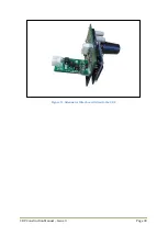
Page 30: ...CDV Construction Manual Issue 3 Page 30 Figure 11 Attenuator filter board fitted to the CDV ...

