MDT Construction Manual – Issue 2
Page 24
Step 6: Non-polarised capacitors
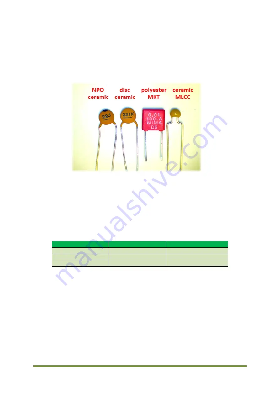
Note the various types as per the examples shown in Figure 12. Ceramic disc NPO, standard
ceramic disc, polyester MKT and ceramic multi-layer chip capacitors (MLCC). These are all non-
polarized and can go in either way. There are 14 x 100nf (0.1uF) MLCC and as they are quite
small install these first.
Figure 12 Non-polarised capacitors
Step 7: Low pass filter capacitors
These look like 0.1uF MLCC types, so don’t get them mixed up.
Figure 13 shows how to identify the LPF capacitor markings.
Capacitor
Marking
Value
C24
151
150pF
C23
221
220pF
C25, C26, C27
471
470pF
Figure 13 LPF capacitor marking
Summary of Contents for MDT
Page 1: ...MDT Construction Manual Issue 2 Page 1 MDT DSB TRANSCEIVER CONSTRUCTION MANUAL ...
Page 8: ...MDT Construction Manual Issue 2 Page 8 5 MDT BLOCK DIAGRAM Figure 3 MDT Block diagram ...
Page 12: ...MDT Construction Manual Issue 2 Page 12 Figure 4 Carrier oscillator ...
Page 13: ...MDT Construction Manual Issue 2 Page 13 Figure 5 Mixer ...
Page 14: ...MDT Construction Manual Issue 2 Page 14 Figure 6 Microphone Amplifier ...
Page 15: ...MDT Construction Manual Issue 2 Page 15 Figure 7 Transmit ...
Page 16: ...MDT Construction Manual Issue 2 Page 16 Figure 8 Receive Audio ...
Page 32: ...MDT Construction Manual Issue 2 Page 32 Figure 20 Component overlay ...


