MST Construction Manual – Issue 1
Page 17
5
C
ONSTRUCTION
5.1
G
ENERAL
The MST is a built on a high quality fiberglass PCB. The PCB is doubled sided with tracks on the
bottom side with the top side being a continuous ground plane. The holes are plated through
and so it is not necessary to solder both sides to make connections. To assist construction the
component overlay is screen printed on the top side and a solder mask is included to guard
against solder bridges.
The ground plane is substantial and can sink quite a bit of heat from low wattage soldering irons
so ensure you use a good quality iron that can sustain the power required. You may find that
sometimes solder doesn’t appear to flow through to the top side. This is not necessarily a
problem because the plated through holes make a connection to the top side automatically.
Another point to consider is that plated through holes consume more solder than non-plated
holes and makes it more difficult to remove components.
The lesson is to double check the values and orientation of components before
installation.
There isn’t a ‘best’ scheme for loading the components. If desired you can build sections at a
time and test them out, but it is not necessary and in any case some sections rely on others
before they will operate. The suggested procedure is to load the smaller components first and
then work upwards.
5.2
C
ONSTRUCTION
S
TEPS
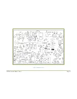
Refer to the parts list and
Figure 7when installing the components.
Step 1: Resistors
Install and solder a few at a time. It is easier and less confusing to install a group with the same
value rather than to cover a section of the PCB with mixed values. If in any doubt about reading
resistor values measure them with a multimeter before soldering.
Pass the pigtails through from the top and bend out slightly underneath to hold them in place.
Turn the PCB over and press down slightly to make them rest against the surface and solder. Cut
off the excess pigtail with side cutters.
Step 2: Diodes
Note the positive or cathode end before installation. The small Zener diodes look like signal
diodes so make sure you don’t get them mixed up.
Step 3: Non-polarized capacitors
Note the various types used. Ceramic disc, ceramic monolithic and polyester MKT. These are
non-polarized and can go in either way.
Summary of Contents for MST400
Page 1: ...MST Construction Manual Issue 1 Page 1 MST CONSTRUCTION MANUAL ...
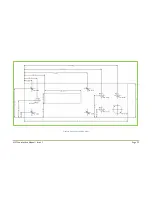
Page 9: ...MST Construction Manual Issue 1 Page 9 Figure 2 SSB generator ...
Page 10: ...MST Construction Manual Issue 1 Page 10 Figure 3 Transmit mixer ...
Page 11: ...MST Construction Manual Issue 1 Page 11 Figure 4 Power amplifier ...
Page 12: ...MST Construction Manual Issue 1 Page 12 Figure 5 Receive mixer ...
Page 13: ...MST Construction Manual Issue 1 Page 13 Figure 6 Receive audio ...
Page 22: ...MST Construction Manual Issue 1 Page 22 Figure 7 Component overlay ...
Page 25: ...MST Construction Manual Issue 1 Page 25 Figure 8 Front panel drilling guide ...


