MST Construction Manual – Issue 1
Page 18
Step 4: Trimmer capacitors and trimpots
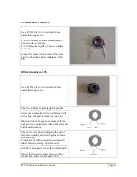
The type specified for the trimmer capacitor is quite small and has one lead electrically
connected to the screwdriver adjustment slot. Use a multimeter to determine this pin and solder
to the hole in the PCB connected to the ground plane.
Note that the carrier balance trimpot is a multi-turn vertical mount while the bias trimpot is a
horizontal mount type.
Step 5: Transistors
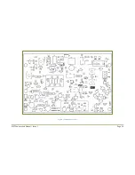
The 2N3904 transistors and 2N7000 MOSFET are orientated to match the screen silk
component overlay. The BD139 is installed so that the metal side of the body faces inwards
towards the centre of the PCB. Leave the IRF510 power MOSFET installation till later.
Step 6: Integrated Circuits
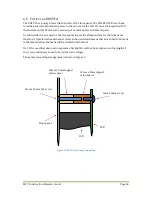
All ICs are 8 pin DIP types and have either a dot above pin 1 or a notch at the top between pin 1
and pin 8. This is shown in the top view diagram below. Double check they are installed in the
correct orientation.
Step 7: Electrolytic capacitors
These are polarized and must go in the correct way. The component overlay has a ‘+’ mark to
indicate the positive lead.
Step 8: Connectors
There are a number of connectors fitted to the PCB to provide a neat finished product. They also
allow easy removal of the PCB if required. The 2.54mm pitch connectors have a vertical
polarizing piece and the connectors are installed with this piece towards the centre of the PCB.
The power connector is a 2 way terminal block and the terminal openings face towards the edge
of the PCB.
The antenna and its ground connection are soldered to a pair of 1mm PCB pins. This is done to
ensure a positive low resistance connection.
Step 9: IF transformers and relay
The four IF transformers can only go in one way and so are simply fitted into the holes in the
PCB and soldered. The relay is inserted into the board and soldered.
1
2
3
4
8
7
6
5
Summary of Contents for MST400
Page 1: ...MST Construction Manual Issue 1 Page 1 MST CONSTRUCTION MANUAL ...
Page 9: ...MST Construction Manual Issue 1 Page 9 Figure 2 SSB generator ...
Page 10: ...MST Construction Manual Issue 1 Page 10 Figure 3 Transmit mixer ...
Page 11: ...MST Construction Manual Issue 1 Page 11 Figure 4 Power amplifier ...
Page 12: ...MST Construction Manual Issue 1 Page 12 Figure 5 Receive mixer ...
Page 13: ...MST Construction Manual Issue 1 Page 13 Figure 6 Receive audio ...
Page 22: ...MST Construction Manual Issue 1 Page 22 Figure 7 Component overlay ...
Page 25: ...MST Construction Manual Issue 1 Page 25 Figure 8 Front panel drilling guide ...

