MST Construction Manual – Issue 1
Page 21
Step 11: Crystals
The crystals are mounted close to the PCB but not touching it. This is to avoid the metal case of
the crystal shorting pads underneath. A space of about 1mm is all that’s needed. Once the
crystals for the filter are installed solder a wire across the top of the metal cases and down to a
spare pad in the PCB groundplane set aside for this purpose. This will help keep out noise and
resist widening of the filter skirts.
Step 12: Antenna wires
The antenna wires are hard to solder to the PCB pins once the PCB is installed in the case so
solder short lengths to the ANT and GND pins now.
Step 13: Power MOSFET
The reason this is left to last is simply because it is near the edge and may get bent and possibly
damaged as the PCB is turned over and back as other components are being installed.
Mount the device with about 5mm of lead length between the PCB and body.
Summary of Contents for MST400
Page 1: ...MST Construction Manual Issue 1 Page 1 MST CONSTRUCTION MANUAL ...
Page 9: ...MST Construction Manual Issue 1 Page 9 Figure 2 SSB generator ...
Page 10: ...MST Construction Manual Issue 1 Page 10 Figure 3 Transmit mixer ...
Page 11: ...MST Construction Manual Issue 1 Page 11 Figure 4 Power amplifier ...
Page 12: ...MST Construction Manual Issue 1 Page 12 Figure 5 Receive mixer ...
Page 13: ...MST Construction Manual Issue 1 Page 13 Figure 6 Receive audio ...
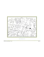
Page 22: ...MST Construction Manual Issue 1 Page 22 Figure 7 Component overlay ...
Page 25: ...MST Construction Manual Issue 1 Page 25 Figure 8 Front panel drilling guide ...


