MST Construction Manual – Issue 1
Page 26
6.5
F
ITTING THE
DDS
VFO
The DDS VFO is simply screwed to the inside of the front panel. The DDS VFO PCB is set back
from the panel using threaded spacers to allow room for the LCD. If you use the specified LCD
the distance will be 22mm and is made up of a 10mm spacer and 12mm spacer.
A countersink screw is used on the front panel to provide a flush surface for the front panel
label to sit. If preferred round head screws can be used which means that holes need to be made
in the label and also the heads will be visible from the front.
If a LCD is used that does not incorporate a backlight it will not be as high and so the length of
the screws and spacers need to be reduced accordingly.
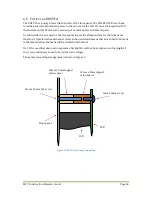
The general mounting arrangement is shown in Figure 9.
Figure 9 DDS VFO front panel mounting
12mm x 3mm tapped
nylon spacer
10mm x 3mm tapped
nylon spacer
3mm x 16mm C/S screw
Front panel
PCB
LCD
3mm x 6mm screw
Summary of Contents for MST400
Page 1: ...MST Construction Manual Issue 1 Page 1 MST CONSTRUCTION MANUAL ...
Page 9: ...MST Construction Manual Issue 1 Page 9 Figure 2 SSB generator ...
Page 10: ...MST Construction Manual Issue 1 Page 10 Figure 3 Transmit mixer ...
Page 11: ...MST Construction Manual Issue 1 Page 11 Figure 4 Power amplifier ...
Page 12: ...MST Construction Manual Issue 1 Page 12 Figure 5 Receive mixer ...
Page 13: ...MST Construction Manual Issue 1 Page 13 Figure 6 Receive audio ...
Page 22: ...MST Construction Manual Issue 1 Page 22 Figure 7 Component overlay ...
Page 25: ...MST Construction Manual Issue 1 Page 25 Figure 8 Front panel drilling guide ...


