MST Construction Manual – Issue 1
Page 29
8
T
ESTING AND ALIGNMENT
8.1
G
ENERAL
A suggested list of basic tools and accessories to undertake testing is shown below.
Digital multimeter.
50 ohm dummy load capable of dissipating at least 5 Watts.
QRP wattmeter or oscilloscope.
Power supply capable of 13.8V DC at 2 Amps.
Small adjustment screwdriver.
An audio signal generator.
An RF signal generator.
A frequency counter.
Obviously an external VFO is required for testing and operation and it is assumed during
the rest of this section that the MST board is being used with the DDS VFO which is
already configured and fully operational.
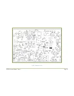
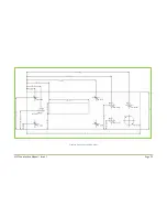
Figure 11 lists typical voltages at various points around the board and can be used to
verify operation.
8.2
P
OWER ON
Temporarily remove the power connector for the VFO so that the MST board current can
be measured alone.
Using a small screwdriver:
o
Rotate the bias trimpot VR2 fully ant-clockwise so that the gate bias voltage is
zero volts.
o
Set the trimmer capacitors to halfway.
o
Set carrier balance trimpot VR1 to halfway by counting turns. You should hear a
slight click as you reach the end.
Connect the power supply to the board terminals.
Double check the polarity is correct
before applying power
.
If your power supply does not include a current meter, connect a multimeter in series
with the power supply positive lead and set to measure current.
Connect a 50 Ohm dummy load to the antenna socket.
Turn on the power supply and note the supply current. It should be around 70mA. If it’s
far from this turn off immediately and look for problems.
The relay should be de-energized and the board in receive mode. To verify that there are
no obvious problems do a quick probe around the board with a multimeter and check
the DC receive voltages as shown in Figure 11.
Plug in the VFO power connector. Check the power supply current. If using the DDS VFO
it should rise to around 150mA but this is highly dependent on the type of LCD used and
the backlight current.
Summary of Contents for MST400
Page 1: ...MST Construction Manual Issue 1 Page 1 MST CONSTRUCTION MANUAL ...
Page 9: ...MST Construction Manual Issue 1 Page 9 Figure 2 SSB generator ...
Page 10: ...MST Construction Manual Issue 1 Page 10 Figure 3 Transmit mixer ...
Page 11: ...MST Construction Manual Issue 1 Page 11 Figure 4 Power amplifier ...
Page 12: ...MST Construction Manual Issue 1 Page 12 Figure 5 Receive mixer ...
Page 13: ...MST Construction Manual Issue 1 Page 13 Figure 6 Receive audio ...
Page 22: ...MST Construction Manual Issue 1 Page 22 Figure 7 Component overlay ...
Page 25: ...MST Construction Manual Issue 1 Page 25 Figure 8 Front panel drilling guide ...


