MST Construction Manual – Issue 1
Page 31
Location
V DC Receive
V DC Transmit
U1 pin 8
+6.8V
0V
U1 pin 5
+5.6V
0V
U2 pin 8
+6.8V
0V
U2 pin 5
+5.6V
0V
U3 pin 7
+13.3V
0V
U3 pin 6
+6.7V
0V
U4 pin 6
+13.7V
0V
U4 pin 5
+6.7V
0V
Q1 collector
9V
9V
Q1 emitter
5.6V
5.6V
Q2 emitter
0V
6V
Q4 emitter
0V
7.2V
Q3 collector
0V
8V
U5 pin 8
0V
+6.8V
U5 pin 5
0V
+5.6V
Q9 emitter
0V
1.5V
Q6 emitter
0V
1.5V
Q7 gate
0V
3.9V
Note readings taken with a power supply voltage of 13.8V DC.
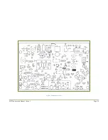
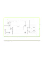
Figure 11 Typical circuit voltages.
Summary of Contents for MST400
Page 1: ...MST Construction Manual Issue 1 Page 1 MST CONSTRUCTION MANUAL ...
Page 9: ...MST Construction Manual Issue 1 Page 9 Figure 2 SSB generator ...
Page 10: ...MST Construction Manual Issue 1 Page 10 Figure 3 Transmit mixer ...
Page 11: ...MST Construction Manual Issue 1 Page 11 Figure 4 Power amplifier ...
Page 12: ...MST Construction Manual Issue 1 Page 12 Figure 5 Receive mixer ...
Page 13: ...MST Construction Manual Issue 1 Page 13 Figure 6 Receive audio ...
Page 22: ...MST Construction Manual Issue 1 Page 22 Figure 7 Component overlay ...
Page 25: ...MST Construction Manual Issue 1 Page 25 Figure 8 Front panel drilling guide ...


