MST Construction Manual – Issue 1
Page 33
9
O
PERATION
Operating the MST is very easy as there are no complicated controls and software menus to
navigate. It’s simply a matter of connecting a power supply, microphone and antenna and
talking. Operation of the DDS VFO is covered in the DDS VFO construction manual.
In receive mode apart from the VFO there is only the AF gain control to adjust. The MST does
not incorporate automatic gain control (AGC) and so you will need to adjust the AF gain control
to even out signals. In practice though you’ll find that you won’t be continually twiddling the
knob and it will only be when stations are either very weak or very strong that you will find it
necessary to make changes.
The MST as described does not include a headphone socket. If you add one yourself make sure
that you include a series limiting resistor to reduce the output of the LM386 otherwise you will
find audio peaks quite uncomfortable.
To transmit press the PTT button on your microphone and talk. The front panel RF LED
indicator will illuminate on voice peaks. It can also be used as a rough guide to power output as
the current through the LED, and therefore its brightness, is dependent on the peak RF output. If
the LED is illuminated at a constant level when talking, it indicates that you are driving the
transmitter too hard and causing clipping of the RF signal.
Overdriving will create distortion and excessive harmonic generation and must be
avoided.
To check your signal either connect the MST to a dummy load and monitor yourself with
headphones on a nearby receiver, or have a friend that lives close by listen to your signal. The
idea is to increase the mic gain progressively while sweeping across your transmission looking
for distortion and unwanted spurious byproducts across the band. Set the mic gain control just
below the point where these are noticeable.
Congratulations your new SSB QRP transceiver is ready to put on the air.
Have fun!
Summary of Contents for MST400
Page 1: ...MST Construction Manual Issue 1 Page 1 MST CONSTRUCTION MANUAL ...
Page 9: ...MST Construction Manual Issue 1 Page 9 Figure 2 SSB generator ...
Page 10: ...MST Construction Manual Issue 1 Page 10 Figure 3 Transmit mixer ...
Page 11: ...MST Construction Manual Issue 1 Page 11 Figure 4 Power amplifier ...
Page 12: ...MST Construction Manual Issue 1 Page 12 Figure 5 Receive mixer ...
Page 13: ...MST Construction Manual Issue 1 Page 13 Figure 6 Receive audio ...
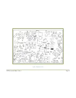
Page 22: ...MST Construction Manual Issue 1 Page 22 Figure 7 Component overlay ...
Page 25: ...MST Construction Manual Issue 1 Page 25 Figure 8 Front panel drilling guide ...


