NOTE:
If the pilot light does not illuminate within 30 seconds the unit may be in a FAULT CONDITION. If this occurs,
the unit should be returned to P.Audio for evaluation.
THERE ARE NO USER-SERVICABLE PARTS INSIDE. DO NOT REMOVE THE AMPLIFIER MODULE!
(See the section below
“Replacement of Components” for more detailed information).
3.2.
AUDIO
CONNECTIONS
The CXP amplifiers include both male and female XLR-type connectors. Any standard XLR-type cable end connectors may be
used.
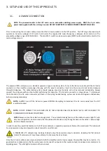
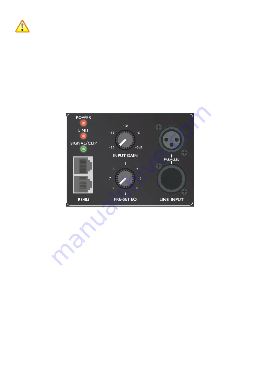
The image below illustrates the inputs found on the amplifier plate. Line Input and Line Output (THRU) are shown. All the
necessary EQ is provided in the on board pre amp. A line level input of voltage 0.775v will drive the on board amplifiers to full
power.
The CXP input section also allows for “paralleling” multiple powered enclosures together. This function is achieved by using the
Line Output XLR-type connector located next to the input XLR-type connector on the amplifier module.
The output level can be
controlled using the level control knob, or using remote software (see section REMOTE SOFTWARE).
For example, if 2 CXP-21Sub and 2 CXP-121C were used for a front of house system, the XLR signal lead can be linked to each
enclosure. The correct preset should then be selected on each enclosure, for example:
CXP-21 Sub: Preset 2 – Flat with CXP-121C/CXP-151C
CXP-121C: Preset 2 – Flat with subwoofer (High Pass at 100Hz)

