Instruction Manual
Updated11/2013
14
| 24
387,2
270,0
135,0
128,0
679,2
580,2
120,0
60,0
290,1
115,0
5.6 mounting the Wallbox
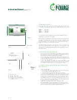
The desired location and position of the Wallbox should be determined prior
to installation. Please take the measurements of the Wallbox Duo into account!
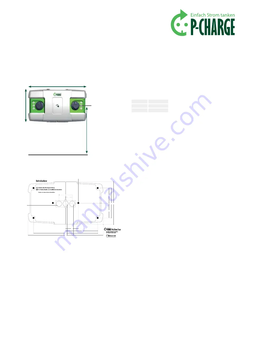
We recommend that the charging points be located at a height of approx.
1300mm above ground level, see
image 5
.
Please be aware of the Wallbox in-wall supply line when positioning the drill-
ing template. The left bushing is for the customer-installed ventilation system,
the middle bushing for the voltage supply line to the Wallbox and the right
bushing for a data cable to the EWS Box, see
image 6
.
The Wallbox should be mounted in a position which allows for optimal access-
ibility by the user. Please ensure that you take into account the position of the
charging sockets on the electric vehicle and that the charging cables are of
appropriate length.
5.6.1 mounting the Wallbox rear panel
1.
Position the enclosed drilling template horizontally in the desired Wall-
box location and secure the drilling template (with tape if necessary) to
the wall. Mark the 6 drill holes with a pencil, see
image 6
.
2.
Remove the drilling template and drill 6 holes using a drill bit with a dia-
meter of 10.0mm. Ensure that the holes are drilled to a sufficient depth to
receive the wall-plugs/dowels.
3.
Fit each of the 6 M8x100 wafer-head screws with a sealing rubber washer.
Position the cable bushing openings at the rubber seals in such a way as
to facilitate the feed-through of your connecting cables
(image 6)
.
from here on, the Wall-mounting shoulD be performeD by at
least tWo people.
4.
Laying the supply lines
a. on-wall: Feed supply lines into the glands (only once rear panel has
been mounted should the glands be secured)
b. in-wall: Feed the connecting cables through the rear panel
5.
One person should now hold the rear panel while the second person fits
the base plate with the housing onto it. Position the rear panel with its
base plate on the prepared wall (drilled holes) and insert each of the 6
M8x100 wafer-head screws into its designated drill hole. The position of
the holes in the wall for the wafer-head screws should correspond to the
positions of the holes drilled in the template.
6.
Tighten the screws lightly with a 6-Lobe screwdriver TX40.
7.
Re-align the Wallbox Duo and fully tighten the screws appropriately.
8.
Connect the Wallbox voltage supply cable to the designated main con-
nection terminal at X1. Check that the terminals are secure.
700 mm
335 mm
1300 mm
Ground level
Image 5
height
335 mm
Width
700 mm
Depth
170 mm
Image 6
6x drilled holes
Bushing - data cable
Bushing - power supply cable
Activation of customer-installed
ventilation system


