Instruction Manual
Updated11/2013
15
| 24
please note
: This task should be performed by qualified personnel only! The
control fuse must be installed only once the mounting work has been complet-
ed! A missing neutral conductor can cause irrevocable damage to the device!
9.
You also have the option to connect your data cable to an Ethernet con-
nection on the EWS Box at slots X301 or X201, to enable connection of
the Wallbox with a server / PC.
10. In the same way the customer-installed ventilation can also be connect-
ed to the EWS Box at contactor terminal X102.
11. Ensure that the cables are strain-relieved.
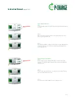
5.6.2 mounting the Wallbox housing
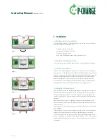
The Wallbox is now securely fixed on the wall. Only the housing remains to be
fitted. The next steps outline how this is to be done:
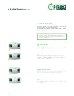
1.
Take the housing in both hands and position parallel to the rear panel.
2.
Next, push the housing from the front up and over the rear panel.
Position the housing carefully to ensure that the slots fit around the
respective cable bushings of the electrical components. Take care not to
damage the seals on the inner side of the housing when doing so.
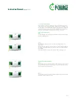
3.
Lightly re-tighten the 8 screws
(image 4)
with sealing washers into the
pre-bored holes.
4.
Align the housing once more and check that the washer seals are correctly
positioned for optimum contact.
5.
Now tighten the 8 screws fully.
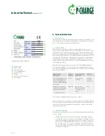
6.
Replace the green front housings / facing. Hook the bevelled outer edges
of the facings into the Wallbox housing and position across the charging
sockets. Then push the facings into place.
7.
Position the front cover from above onto the Wallbox and push down
into the housing.
8.
To close the Wallbox completely, push the sliding lock cylinder back into
the casing.
9.
Remove the red protective rubber strip from the underside of the housing.
10. Your Wallbox Duo is now fully installed and can be used to charge electric
vehicles.


