www.p-light.com
established 2000
Elektronics
8
Elektronic terminals
Terminal no.
Description
1. B24V, connected to P-LIGHT battery.
2. Battery Gnd (-), connected to P-LIGHT battery.
3. Input Gnd (-) negative/ground, min 2.5 mm². From vehicle/
trailer hitch.
4. Input +24V “Lighting circuit 1”, min 2.5 mm². From the trailer’s
electric connector.
5. 24V “Lighting circuit 1”, connected to parking and
side lights which are to remain on while driving, and P-LIGHT
for short-term parking.
NOTE: Must not be connected to cabling connected to
terminal 4 or 6.
6. Input +24V “Lighting circuit 2”, min 2.5 mm². From the trailer’s
electric connector.
7. 24V “Lighting circuit 2”, connected to parking and
side lights which are to remain on while driving, and P-LIGHT
for short-term parking.
NOTE: Must not be connected to cabling connected to
terminal 4 or 6.
8. Input +24V “Option”. (Direct operation to terminal 9, if, for
example, you connect the warning light to terminal 9, it’s
possible to connect the trailer’s reversing circuit here, this
activates the warning light when the vehicle reverses).
9. 24V “Option” e.g. warning light, work lighting, etc.
max. 200W. Activated by push button 2.
10. 24V “AUX”. 24V even if the truck is not
connected, nor controlled by any pushbutton. Is intended for
operation of e.g. external radio control, the cable is prepared
up to the rocker switch where you connect the required
equipment. Max 200W. Factory connected to terminal 31.
21 and 22. No function.
23. Input +24V from pushbutton 2 “Option” (activates terminal 9).
24. 24V to pushbutton 2 “Option”.
25. Input +24V from pushbutton 1 “Parking” (activates terminals
5 and 7).
26. 24V to pushbutton 1 “Parking”.
30. 24V Toggle switch. See wiring diagram (factory-
connected from terminal 31).
31. 24V to toggle switch for external radio control
(factory connected from terminal 10) AUX.
32. 24V Toggle switch. See wiring diagram (factory-
connected from terminal 30).
Extra switch. Toggle switch. See wiring diagram (factory-
connected from terminal 32).
Note, terminals 30, 31 and 32 are monitored by voltage
monitors, and one of these must always be used for the
connection of equipment in order to prevent deep discharge
of batteries and risks of damage to connected equipment due
to excessively low voltage during operation.
34. Ground point power Gnd(-), cable dimension after power
on (Cable to the negative terminal of the battery is factory
mounted).
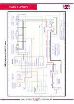
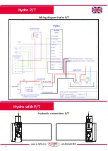
41. See wiring diagram, see pages 18-20.
42. See wiring diagram, see pages 18-20.
43. See wiring diagram, see pages 18-20.
44. See wiring diagram, see pages 18-20.
45. Connection point for expanded charging (30A), cable mounted
on both truck and trailer, recommended 4 mm². Factory
connected to terminals 4 and 6 on control units 2 and 3. NB!
only on models with 30A charging. Applies to Magnum only.
F1. See wiring diagram, see pages 18-20.
Connection P-LIGHT® electronics box
Use RKKB cable for connection of P-LIGHT® To ensure full
charging and function, the wires between the trailer’s
coupling glove (to truck) and P-LIGHT® connectors 3,
4 and 6 on the electronics box must be min 2.5 mm².
There is also an advantage if the truck has a 2.5 mm²
wire to the coupling glove, but not less than 1.5 mm².
Wires for other couplings are dimensioned to suit the
consumption connected.
When more electronics boxes are mounted for 30 A
charging, min 6 mm² cable should be mounted on both
truck and trailer, up to connection point 33 and 45 and
reinforce Gnd (-) from the trailer chassis to earth point
33.


