background image

3

1. Application.

RK-2001AT2 controller is a device designed for temperature control of solid fuel

fired boilers. The temperature of the boiler is kept on level set by user, by controlling

the speed of the pressure fan. The controller monitors temperature of water in the

boiler, displays it on the display, and controlls circulating pump. The controller has

been equipped with additional thermostat and sensor input. This thermostat can be

used to set room temperature or desired exhaust gas temperature. Depending on

chosen solution, room temperature sensor or exhaust gas temperature sensor should

be connected to the additional sensor input. The device also design allows for

connecting external contact thermostat instead of room temperature sensor.

2. Connection.

Before turning on the device by master switch, connect controller, pressure fan and

circulating pump power cords to appropriate sockets in the rear of the controller.

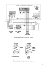
Temperature sensor should be placed in measurement hole in the boiler. Picture 2

shows diagram of electrical connection of the device.

WARNING!

Before plugging the device to the power source check if it is proprerly

grounded and if the screws of the connector are properly screwed.

CAUTION!

The maximum total power of devices connected to the controller mustn't

exceed 450W.

CAUTION!

As additional option you can connect the UM-1 module to the controller

that allows controlling the additional boiler or the hot water loading pump. It is

necessary to protect the power supply of these devices with suitable cut-outs.

Not used power outs of the controller may remain unconnected.

3. Operation.

After turning the device on, all the elements of the display are lit for a while to check

if they are working properly. The controller, when power appears, returns to its last

state before turning off or power loss.

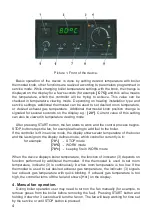
Front of the device (Picture 1) consist of:

1 - Master switch,

2 - Display, indicating boiler temperature and parameters,

3 - Room thermostat or exhaust gas thermostat indicator,

4 - Boiler thermostat knob,

5 - Additional thermostat knob,

6 - STOP/choose parameters/erase alarms button,

7 - START/choose parameters button,

8 - Start programming in service mode/confirm settings button,

9 - Circulating pump indicator,

Summary of Contents for RK-2001AT2

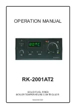
Page 1: ...OPERATION MANUAL SOLID FUEL FIRED BOILER TEMPERATURE CONTROLLER RK 2001AT2 Version AC22...

Page 2: ...r starts in HEATING UP mode This mode turns off influence of exhaust gas thermostat on the fan and central heating pump HEATING UP is active until exhaust gas temperature achieves temperature set with...

Page 3: ...shows diagram of electrical connection of the device WARNING Before plugging the device to the power source check if it is proprerly grounded and if the screws of the connector are properly screwed CA...

Page 4: ...on stops the fan for example allowing to add fuel to the boiler If the controller isn t in service mode the display shows water temperature of the boiler and the last sign on the display defines mode...

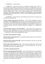
Page 5: ...splays current measured room or exhaust gas temperature 6 Setting up the parameters service mode Holding OK button for more than 3 seconds causes change to service mode where you can view and change p...

Page 6: ...ng pump turn off delay 1 99 1min 2 L 65 Minimum boiler temperature 60 65 1 C 65 H 90 Maximum boiler temperature 80 95 1 C 90 h 5 Boiler temperature hysteresis 1 10 1 C 5 A105 Boiler overheating temper...

Page 7: ...meter value in range from 0 to 10 means time in minutes of the smooth fan speed increase from 40 to value of for smooth boiler start Fan work time n 5 time of turning the fan on for a while to remove...

Page 8: ...ion Central heating pump turn off delay Pd 2 central heating pump stopping too early can cause temperature rise in the boiler and cause its overheating This parameter allows setting central heating pu...

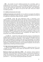
Page 9: ...described above When contacts are open the controller will keep minimum boiler temperature Attention When external thermostat is connected in place of room temperature sensor the temperature set with...

Page 10: ...ing boiler start Fuel shortage testing time in work mode Fb30 time set with this parameter is used when testing fuel shortage after boiler has started Setting this parameter to disables fuel shortage...

Page 11: ...are working correctly After detection of fault it stops the pressure fan turns on the circulating pump and shows proper error message on the display In case of failure please turn off the controller p...

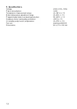
Page 12: ...urement range 9 109 C 1 C Boiler temperature adjustment range 30 90 C 1 C Programmable boiler overheating protection 90 99 C 1 C Hardware boiler overheating protection 95 C 1 C Circulating pump launch...

Page 13: ...13 Picture 2 RK 2001AT2 connection scheme Picture 3 UM 1 module connection scheme...

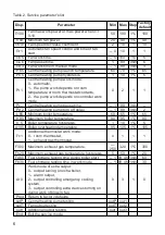
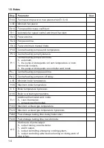
Page 14: ...controller work mode Pc Central heating pump pause time Pd 2 Central heating pump turn off delay L 65 Minimum boiler temperature H 90 Maximum boiler temperature h 5 Boiler temperature hysteresis A105...

Page 15: ......

Page 16: ...Producer P W KEY 11 200 Bartoszyce ul Bohater w Warszawy 67 tel 89 763 50 50 fax 89 763 50 51 www pwkey pl e mail pwkey onet pl...

Reviews: