background image

Maintenance & Care

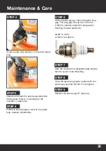
Using a spark plug spanner, remove the spark 
plug.

STEP 2

Inspect and clean the spark plug electrode, 
making sure there is no damage to the 
insulator or electrode.

STEP 3

If there is any damage or wear to the spark 
plug, replace immediately.

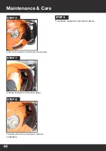
STEP 4

00.28” to 0.031”
0.70mm to 0.80mm

Refit the cleaned and adjusted spark plug by 
hand to avoid cross-threading.

STEP 7

Once the spark plug seats, tighten with the 
spark plug spanner DO NOT over tighten.

STEP 8

Replace the spark plug HT lead cap.

STEP 9

Using a feeler gauge, check the spark plug 
gap. The plug gap should be 0.70mm to 
0.80mm, carefully adjust the plug gap by 
bending the side electrode.

STEP 5

  35

Summary of Contents for P5100SPE

Page 1: ...P1 Petrol Lawn Mower P5100SPE User Manual...

Page 2: ...e of production however P1 Power Equipment may make modifications to the product without notification GENPOWER LTD Isaac Way London Road Pembroke Dock UNITED KINGDOM SA72 4RW T 44 0 1646 687 880 F 44...

Page 3: ...chment 17 OPC Cable Adjustment 18 Before Each Use 22 Starting The Lawnmower 22 27 After Each Use 28 Stopping The Lawnmower 28 Checking Oil Level 16 Filling The Fuel Tank 16 Specifications 29 Troublesh...

Page 4: ...3 OPC Operator Presence Control Lever 4 Throttle Lever 5 Handle Quick Release 6 Lower Handle 7 Fuel Filler Cap 8 Air Filter 9 Spark Plug 10 Exhaust 11 Side Discharge Cover 12 Side Discharge Chute 13...

Page 5: ...ne during operation If approached stop the machine immediately PROTECT FROM MOISTURE Do not expose the product to rain or wet conditions WEEE SYMBOL Waste electrical products should not be disposed of...

Page 6: ...ponsibilty of the user to assess the po tential risk of the area where work is being Preliminary Operations 1 Always wear anti slip and resistant work footwear and long pants while using the machine D...

Page 7: ...f the machine before using and in particular Check that the screws and cutting unit are not worn or damaged and check the appearance of the blade Replace the entire blade and all worn or damaged screw...

Page 8: ...dentify electrical isolation methods and isolate all electrical supplies Prior to use and with all electrical supplies isolated you MUST check all electrical cables plugs and connectors for the follow...

Page 9: ...n well ventilated areas There is an explosion risk if the battery terminals are short circuited when connecting disconnecting ALWAYS exercise great care so that the terminals or battery leads are NOT...

Page 10: ...tely or go to Hospital let them know that you suspect carbon monoxide poisoning DO NOT use in an enclosed area or moving vehicle 2 You must only work in daylight or with good artificial light in good...

Page 11: ...e chute Before cleaning checking or working on the machine After striking a foreign object you must inspect the machine for damage and make repairs before using it again 25 Disengage the blade and tur...

Page 12: ...y precaution is only effective when it is followed exactly Intended Use This machine was designed and manufactured for cutting and collecting grass in gardens and grassy areas in areas in proportion t...

Page 13: ...nmower can be supplied with some parts already assembled Prior to assembly check all items have been received WARNING Unboxing and assembling the lawnmower should be done on a flat stable surface with...

Page 14: ...oil retaining loop STEP 7 Lift the rear discharge flap and remove the mulching plug if installed STEP 8 Using the hooks on the grass bag hook the grass bag over the corresponding plastic moulding at t...

Page 15: ...s on how to do this are on the next page STEP 12 Make sure you attach the cables and adjust the OPC and drive cables Instructions on how to fo this are on pages 17 18 and 19 STEP 10 Set the cutting he...

Page 16: ...ft in the machine so please fill with caution Adding Fuel CAUTION ALL FUELS ARE FLAMMABLE ALWAYS fuel and defuel in a well ventilated area outside of buildings and away from any possible sources of ig...

Page 17: ...ne STEP 1 Gently push the handle free from its locating hole on the main handlebar STEP 2 Insert the end of the cable in to the location hole on the lever STEP 3 Follow the curve of the cable until th...

Page 18: ...en both nut securely If not repeat the process until the lawn mower will start NOTE It is necessary as part of routine maintenance to adjust the OPC cable tension to ensure the lawnmower will start co...

Page 19: ...e the drive cable down towards the gearbox of the lawn mower until you reach to drive cable adjuster STEP 2 Undo the lock nut and wind away from the adjuster nut STEP 3 Undo the lock nut and wind away...

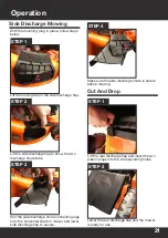
Page 20: ...ver the bar at the rear of the lawn mower STEP 3 Lower the rear discharge flap until it rests on the grass bag STEP 2 STEP 1 Lift the rear discharge flap and remove the grass collector STEP 2 Insert t...

Page 21: ...onto the horizontal shaft on mower and lower side discharge flap to secure STEP 4 Make sure the side discharge chute is secure before mowing Side Discharge Mowing With the mulching plug in place foll...

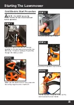
Page 22: ...o page 16 for instructions Check the OPC cable if there is more than 10mm movement in the OPC lever before the cable begins to move then the OPC cable will require adjustment Go to page 18 for instruc...

Page 23: ...s the main handle STEP 5 Gently pull the recoil start handle until you feel resistance Then pull the handle swiftly until the lawn mower starts STEP 3 Push the choke lever fully forward STEP 6 Allow t...

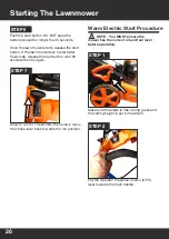
Page 24: ...d the cutting height is set to maximum NOTE You MUST ensure the mower has the correct oil and fuel level before operation Make sure the choke lever is in the start position STEP 2 Gently pull the reco...

Page 25: ...12V charger supplied for 5 hours before first use and then after every 10 uses on average Plug battery charger into battery socket STEP 2 Make sure the blade is free of long grass and the cutting heig...

Page 26: ...e start button wait 30 seconds then try again Allow to run for 15 seconds then slowly move the choke lever back towards the run position STEP 7 Warm Electric Start Procedure STEP 1 NOTE You MUST ensur...

Page 27: ...tart position STEP 3 STEP 4 Push the start button DO NOT keep the button pressed for longer than 5 seconds Once the lawn mower starts release the start button If the lawn mower fails to start after 5...

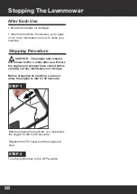
Page 28: ...topping the machine you must allow the engine to idle for 30 seconds Release the OPC Lever and the engine will stop CAUTION The engine and exhaust will remain hot for a while after use Ensure the engi...

Page 29: ...tting Height 25 75mm 6 Heights Cutting Width 508mm 51cm Grass Collector Type Polyester Plastic Grass Collector Volume 60L Deck Material Treated Steel Wheel Size Front 200mm Wheel Size Rear Measured So...

Page 30: ...tive Spark plug gap is incorrect Air filter element is dirty Fit new correctly gapped spark plug Set plug to 0 7 0 8mm Clean or replace air filter element Engine idles poorly Air filter element is dir...

Page 31: ...achine may cause accidents or personal injuries for which the Manufacturer is under no circumstance liable or responsible Part Part Number Blade P5100SPEBLADE Cable P5100SPECABLE Recoil Start P5100SPE...

Page 32: ...ed 7 When handling disassembling and re assembling the blade make sure to wear work gloves 8 Keep the blade well balanced during sharpening All work on the blade disassembly sharpening balancing re as...

Page 33: ...prevent damaging them and remove all traces of spilled petrol immediately The warranty will not cover damage to plastic parts caused by petrol 6 Use the water hose attachment to clean the internal pa...

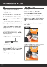
Page 34: ...600ml The oil must be checked before every use We recommend doing an oil service at least once a year more frequently during periods of heavy use 1 Disconnect the spark plug HT lead cap and with the...

Page 35: ...ug replace immediately STEP 4 00 28 to 0 031 0 70mm to 0 80mm Refit the cleaned and adjusted spark plug by hand to avoid cross threading STEP 7 Once the spark plug seats tighten with the spark plug sp...

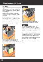
Page 36: ...lead cap Push down the latch tabs on the side of the air filter box to reveal the air filter as seen below STEP 1 Remove the air filter and ensure no dirt or debris can enter the carburetor chamber S...

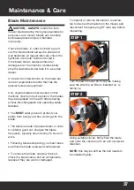
Page 37: ...e with others having similar interchangeable and operating safety features You MUST wear gloves to protect your hands from being cut when working with the blade The blade is made of pressed steel in o...

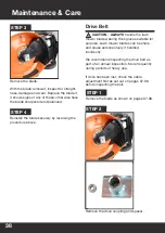
Page 38: ...CAUTION ALWAYS handle the lawn mower blade wearing thick gloves suitable for purpose Lawn mower blades can be sharp and cause personal injury if handled incorrectly We recommend inspecting the drive...

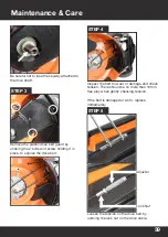
Page 39: ...w holding it in place to expose the drive belt STEP 3 Inspect the belt for wear or damage and check tension There should be no more than 10mm free play when gently checking tension If the belt is dama...

Page 40: ...ce Care Unhook the belt from the main drive pulley STEP 6 Unhook the belt from the rear pulley STEP 7 The belt should now be free to remove completely STEP 8 To reinstall reverse the procedure above S...

Page 41: ...e drain screw 3 Allow all the fuel to drain before reinstalling the drain plug screw Drain Bolt Cleaning CAUTION DO NOT use a hose pipe or pressure washer to clean the engine Water can damage the engi...

Page 42: ...tor 2 Drain the oil from the engine as set out on page 16 3 With the lawn mower drained of all fluids follow the cleaning instructions as set out on page 41 4 Follow the maintenance section and check...

Page 43: ...Civic Amenity Site For further information please contact your local Authority for disposal advice You MUST make sure that all unused oil and fuel is disposed of correctly either beforehand Maintenan...

Page 44: ...medium height setting Summer June July August Mow twice a week under good growing conditions on a low setting In dry conditions mow once a week on a medium to high height setting Autumn September Oct...

Page 45: ...ance We reserve the right to make any modifications without prior notice whenever necessary If you are returning your product please contact the dealer for their returns policy Returning Your Product...

Page 46: ...46 Notes...

Page 47: ...Notes 47...

Page 48: ...48 Notes...

Page 49: ...Notes 41 49...

Page 50: ...Phone Model Number Serial Number As soon as you have purchased the machine we recommend that you fill out the following If you need to contact an authorised dealer or customer service for information...

Page 51: ...ty with the applicable requirements of the following documents EN ISO 3744 2010 EN ISO 11094 1991 EN ISO 5395 1 2013 EN ISO 5395 2 2013 EN ISO 14982 2009 Notified Body T V SUD Shanghai Branch Product...

Page 52: ...porter GENPOWER LTD Isaac Way London Road Pembroke Dock UNITED KINGDOM SA72 4RW T 44 0 1646 687 880 F 44 0 1646 686 198 www p1pe co uk Imported Distributed by Genpower Ltd for The United Kingdom Irela...

Reviews: