6 |
P a g e
41. Power for the Main Circuit GND
42. Power for the Main Circuit
+10V.. +36V
DC
Table 1: FNIP-6x2AD terminal connections
Wiring
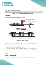
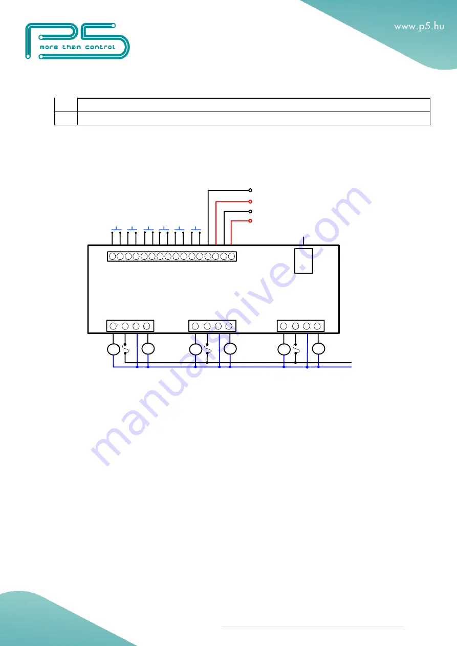
A typical wiring diagram is shown in Figure 3.
Figure 3. Wiring diagram
All line inputs must be on the same phase and on the same circuit breaker!
Recommended wire types
Ethernet cable: Twisted pair, CAT5 or better.
Outputs: According to the loads attached to the outputs (current and voltage).
Inputs: A pair of low or high voltage cables. The inputs use low voltage signals.
Mains/line voltage wiring must be kept physically separated from Ethernet and signal
wiring.
Power requirements
The module requires
10V DC – 36V DC
through terminals 41 and 42.
N L N N
Light
1
Light
2
N L N N
Light
3
Light
4
N L N N
Light
5
Light
6
Local inputs
+10V
– 36V DC for the inputs
+10V
– 36V DC for the main circuit
Ethernet
FNIP-6x2AD


