background image


F o r m   X X X X :                                                                             R e v i s e d   A u g u s t ,   2 0 1 5  


Page 22 

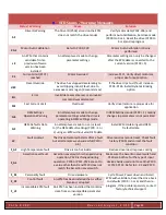
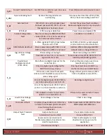
F_cFt 

Forced Translation fault  An EPM from an old drive put into a new 

drive 

Press [M] (mode button) twice to reset 

F_dbF 

Dynamic Braking fault 

Dynamic braking resistors are 

overheating 

Increase active decel time (P105, P126, 

P127), Check main voltage and P107 

F_EF 

External fault 

P121-P124 = 21 and that digital input 

has been opened, P121-P124 = 22 and 

that digital input has been closed 

Correct the external fault condition, 

Make sure digital input is set properly for 

NC or NO circuit 

F_F1 

EPM fault 

EPM missing or defective 

Power down and replace EPM 

F_Fnr 

Control Configuration 

fault 

The drive is setup for REMOTE KEYPAD 

control (P100 = 2 or 5) but is not set up 

for network communication 

Set P400 = 1 or P600 = 1 

4-20mA signal (at TB-25) drops below 

the value set in P164 

Set P400 or P600 to a valid network 

communications protocol selection 

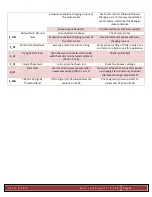
F_GF 

OEM Defaults data fault 

Drive is powered up with P199 = 1 and 

OEM settings in the EPM are not valid 

Install an EPM containing valid OEM 

defaults data or change P199 to 0 

F_HF 

High DC Bus Voltage 

fault 

Mains voltage is too high 

Check main voltage and P107 

Decel time is too short, or too much 

regen from the motor 

Increase decel time (P105, P126, P127) or 

install Dynamic Braking option 

F_IL 

Digital Input 

Configuration fault 

(P121-P124) 

More than one digital input set for the 

same function 

Each setting can only be used once 

(except setting 0 and 3) 

Only one digital input configured for 

MOP function (up, Down) 

One input must be set to MOP up, 

another must be set to MOP down 

PID mode is entered with set point 

reference and feedback source set to the 

same analog signal 

Change PID set point reference (P121-

P124 or feedback source (P201) 

One of the digital inputs (P121-P124) is 

set to 10 and another is set to 11-14 

Reconfigure digital inputs 

One of the digital inputs (P121-P124) is 

set to 11 or 12 and another is set to 13-

14 

PID enabled in Vector Torque mode 

(P200 = 1 or 2 and P300 = 5) 

PID cannot be used in Vector Torque 

mode 

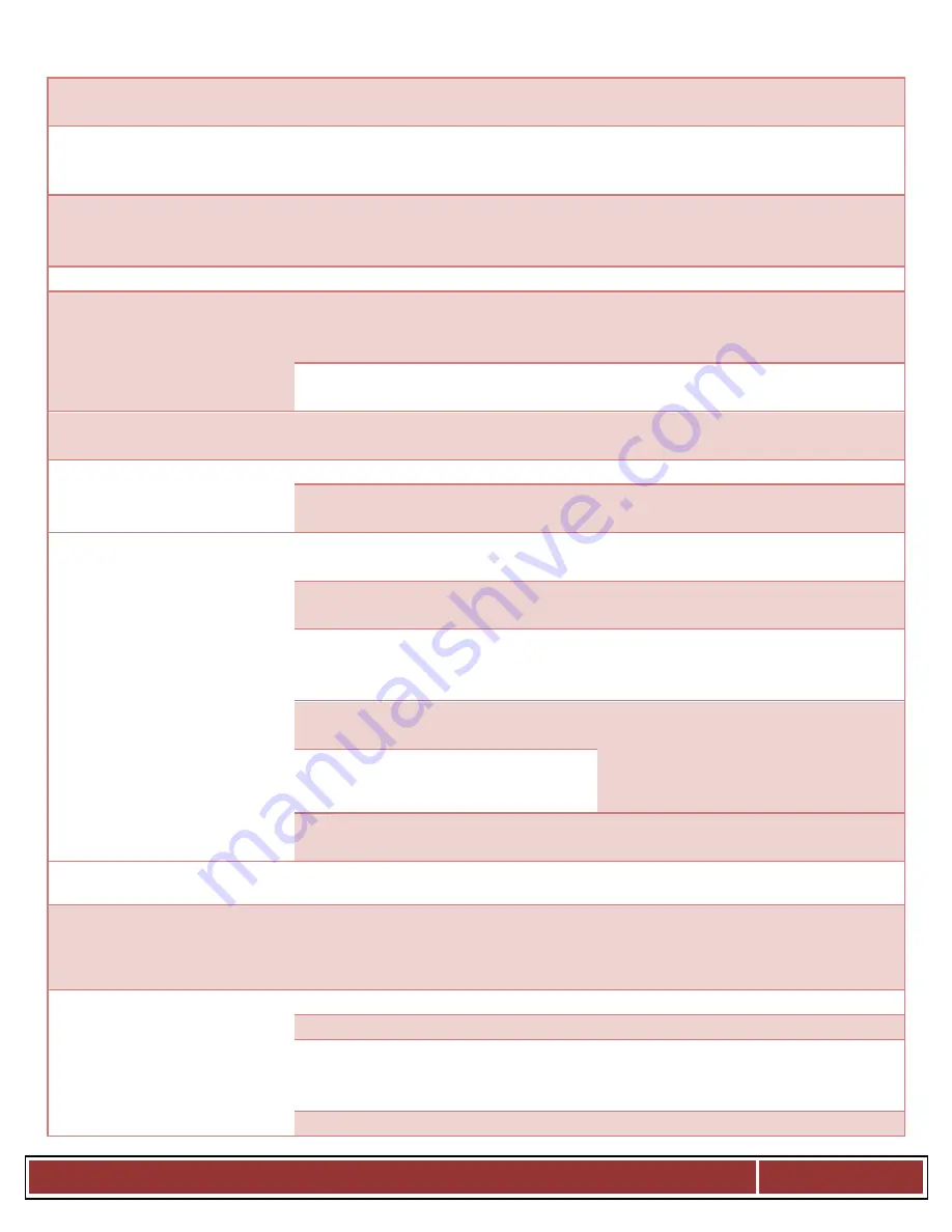
F_LF 

Low DC Bus Voltage 

fault 

Main voltage is too low 

Check main voltage 

F_nId 

No Motor ID fault 

An attempt was made to start the drive 

in Vector or Enhanced V/Hz mode prior 

to performing the Motor Auto-

Calibration 

Refer to parameters P300-P399 for Drive 

Mode setup and calibration 

F_OF 

Output fault: Transistor 

fault 

Output short circuit 

Check motor/motor cable 

Acceleration time too short 

Increase P104, P125 

Severe motor overload due to: 

Mechanical problem, Drive/motor too 

small for application 

Check machine/system, Verify 

drive/motor are proper size for 

application 

Boost values too high 

Decrease P168, P169 

Summary of Contents for PR4,6/SS49

Page 1: ...F o r m X X X X R e v i s e d A u g u s t 2 0 1 5 Page 1 Dual Pallet Reel Straightener Models PR4 6 SS49 PR4 6 SS89 PR4 6 SSP29 49 69 ...

Page 2: ...4 Loading 6 3 5 Base Arm Adjustment 7 3 6 Control Head Height Adjustment 7 3 7 Counter Weight Tension System 7 4 Maintenance 7 4 1 Lubrication 8 5 Troubleshooting 8 6 Specifications 9 6 1 Overall Model Specifications 9 6 2 Parts List 10 7 VFD Status Warning Messages 21 Thank you for selecting our product for your coil handling needs This manual will provide you with all the information necessary t...

Page 3: ...rovides information to assist you in properly adjusting and maintaining your equipment There is no short cut to proper safety therefore it is recommended that you comply with their recommendations at all times 1 2 Warning This equipment offers various means of operating or controlling machines The operator must not be in or near the point of operation of the machine or the operating parts of any e...

Page 4: ...ant in Bloomfield Connecticut The defective part must be forwarded to our plant freight prepaid for our inspection prior to replacement or repair EXCEPT AS EXPRESSLY PROVIDED HEREIN THIS WARRANTY IS IN LIEU OF ALL OTHER WARRANTIES EXPRESS OR IMPLIED INCLUDING A WARRANTY OF MERCHANTABILITY OR FITNESS FOR A PARTICULAR PURPOSE Furthermore the seller does not warrant or represent that the equipment co...

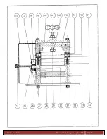
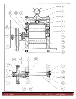
Page 5: ...s is for the customer to connect their e stop connection in conjunction with the palletizer 3 Setup and Operation 3 1 Stock Guiding Stock Guiding is adjusted on the inlet side of the stock straightener Use a strip of the material to be straightened for this adjustment Position the strip between the two inlet roller guides Refer Item 56 This is done by loosening the two screws Refer Item 57 centeri...

Page 6: ...e locknuts Refer Item 19 This bottom stop adjustment allows the raising of head for material starting and positive re positioning NOTE The pointer should read the same as the material thickness in theory at the exit end Adjustment will vary in relation with material thickness and cold work Straightening test should not be performed more than two or three times on the same test strip for reactions ...

Page 7: ...ystem Begin operation with two weights on each cable Pull cable upwards through top of Weight Channel Weights are easily added or removed by positioning the Cable Toggle to slip weights on or off Extra weights are stored on the Base Arm The weight on the cables should be sufficient to draw the Guide Drum back to the off position when material demand stops Weight tension should not be so great as t...

Page 8: ...or other light machine oil Straightener if running all the time one pump of grease every week should be sufficient 5 Troubleshooting Please call our service department at 860 243 8306 for any questions you may have This dual pallet reel is equipped with tight loop and end of strip When the unit receives either input you will have to press the reset button to clear the fault Tight Loop To clear the...

Page 9: ...56 220 1 60 PR4 SSP29 4000 1800 2 50 005 040 0 1 1 0 36 915 3 24 42 1070 3 4 0 56 220 1 60 PR4 SSP49 4000 1800 4 100 005 040 0 1 1 0 36 915 3 24 42 1070 3 4 0 56 220 1 60 PR4 SSP69 4000 1800 6 150 005 030 0 1 1 8 36 915 3 24 42 1070 3 4 0 56 220 1 60 PR6 SS49 6000 2700 4 100 015 065 0 4 1 6 36 915 3 16 52 1325 1 5 1 12 220 1 60 PR6 SS89 6000 2700 8 200 018 065 0 5 1 6 36 915 3 16 52 1325 1 5 1 12 ...

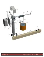
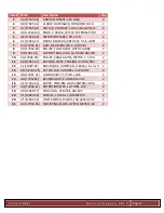
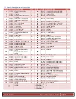
Page 10: ...W 4 15 AO 12133 61 BEARING 2 BOLT FLNG 1 00 BORE CLMP RNG 2 16 AP 16035 10 DISC LEXAN 18in DIA X 2 5 ID 4 17 AQ 16254 04 SHAFT MOTOR EXTENSION SLIP CLUTCH DRVE 2 18 AR 15184 06 SPACER SLIP 2 19 AS 14977 KNOB 2 38 DIA x 3 8 16 THD x 1 0 LONG 2 20 AT 15179 FRICTION DISC 2 21 AU 12442 14 SPRING 1 50 OD x 2 5 FREE LENGTH 2 22 AV 15184 CLUTCH RING OUTER 2 23 AW 14465 08 03 KEEPER DISC HUB FOR 2 0 DIA S...

Page 11: ...F o r m X X X X R e v i s e d A u g u s t 2 0 1 5 Page 11 ...

Page 12: ...F o r m X X X X R e v i s e d A u g u s t 2 0 1 5 Page 12 ...

Page 13: ...DE WITH FLANGE 2 9 AI 17941 01 SUPPORT BAR AXLE 6in DRUM ROLLER 2 10 AJ 17946 03 PULLEY CABLE GUIDE METRIC 1 5 DIA 2 11 AK 17951 07 BACKING PLATE TENSION LC ARM PR4 2 12 AL 12087 07 ENCLOSURE HOFFMAN A 604SC 6 x 4 x 3 2 13 AM 12441 21 SET COLLAR 50 BORE x 437 WIDE 4 14 AN 17961 01 LINEAR SHAFT 1 2 OD x 20in 2 15 AO 1793285 BEARING BLOCK LINEAR GUIDE 2 16 AP 17963 04 COVER TENSION LOOP CONTROL ARM ...

Page 14: ...F o r m X X X X R e v i s e d A u g u s t 2 0 1 5 Page 14 ...

Page 15: ...F o r m X X X X R e v i s e d A u g u s t 2 0 1 5 Page 15 ...

Page 16: ...F o r m X X X X R e v i s e d A u g u s t 2 0 1 5 Page 16 ...

Page 17: ...F o r m X X X X R e v i s e d A u g u s t 2 0 1 5 Page 17 ...

Page 18: ...F o r m X X X X R e v i s e d A u g u s t 2 0 1 5 Page 18 ...

Page 19: ...F o r m X X X X R e v i s e d A u g u s t 2 0 1 5 Page 19 ...

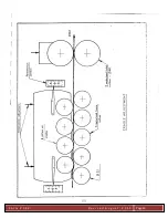
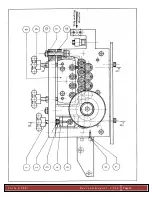
Page 20: ...22 52 05 256 Pinion on pinch shaft 1 17 05 206 05 208 Bridge model SS49 Bridge model SS69 1 1 53 55 942 3 mm nut 1 18 54 802 Washer 10 mm 2 54 55 943 3 mm washer 1 19 54 803 Washer 10 mm 2 55 05 318 Spacer 1 20 05 014 05 016 Top cradle plate model SS49 Top cradle plate model SS69 1 1 56 50 035 Bearing 1 21 51 018 Bearing 12 12 22 57 55 229 8 x 20 cap screw 1 22 05 020 05 023 Upper roll model SS49 ...

Page 21: ...to change parameter settings while the drive is operating in OEM settings mode In OEM Settings mode P199 1 making changes to parameters is not permitted GF OEM Defaults Data Warning An attempt was made to use or reset to the OEM default settings P199 1 or 2 using an EPM without valid OEM data Install EPM containing valid OEM Defaults data LC Fault Lockout The drive attempted 5 starts after a fault...

Page 22: ...rease decel time P105 P126 P127 or install Dynamic Braking option F_IL Digital Input Configuration fault P121 P124 More than one digital input set for the same function Each setting can only be used once except setting 0 and 3 Only one digital input configured for MOP function up Down One input must be set to MOP up another must be set to MOP down PID mode is entered with set point reference and f...

Page 23: ...F_PF Motor Overload fault Excessive motor load for too long Verify proper setting of P108 Verify drive and motor are proper size for application F_rF Flying Restart fault Controller was unable to synchronize with the motor during restart attempt P110 5 or 6 Check motor load F_SF Single Phase fault A line phase has been lost Check line phases voltage F_UF Start fault Start command was present when ...

Reviews: