1
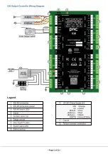
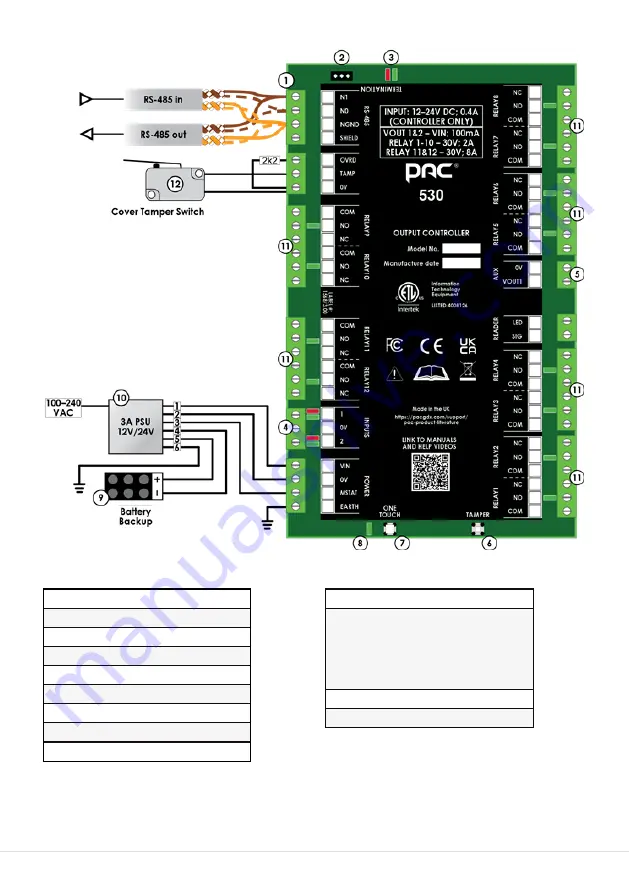
RS-485 connection
2
RS-485 termination jumper
3
RS-485 status LEDs
4
Inputs
5
Auxiliary power out
6
Tamper switch
7
One-Touch™ button
8
System status LED
9
Battery backup
10
12V/24V Power Supply Unit
VIN
0V
MSTAT
(Battery) +
(Battery) –
EARTH
1 Orange
2 White
3 Pink
4 Red
5 Black
6 Green/Yellow
11
Outputs
12
Tamper override / connection
530 Output Controller Wiring Diagram
Legend
– Page 3 of 22 –

