Pacific Accessory Corporation - 1502 S. Santa Fe Street, Santa Ana, CA 92705
Techsupport@pac-audio.com • www.pac-audio.com
12-4-2007
J1850
Class 2
VPW
Class 2
J1850
1 0 0 0 1 1 1 0 1 1 1 1 0 0 1 0 0 1 1 0 1 1 0 0
1 1 1 0 1 0 0 0 0 1 1 0 1 1 0 1 1 1 0 0 1 1 0 0
Arbitration
EOD
CRC
1 0 0 0 1 1 1 0 1 1 1 1 0 0 1 0 0 1 1 0 1 1 0 0
1 1 1 0 1 0 0 0 0 1 1 0 1 1 0 1 1 1 0 0 1 1 0 0
Class 2
Class 2
J1850
VCI-GM3
Video Camera Interface Kit for the
GM Full Size Truck & SUV
Navigation Radios
This interface will
ONLY
work in these vehicles -will
NOT
work with any other GM navigation radios
DISCLAIMER: Under no circumstances shall the manufacturer or the distributors of the VCI-GM3 parts be held liable for consequential
damages sustained in connection with the VCI-GM3. The manufacturer and it’s distributors will not, nor will they authorize any representative
or any other individual to assume obligation or liability in relation to the VCI-GM3 other than its replacement.
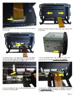
1) With the navigation unit on, press the “Change Map Cover-
age” option under the “Nav” menu and eject the navigation
disc.
WARNING! Wait for the Map Disc to eject and set
aside. Failure to eject the Map Disc will cause failure of
the navigation DVD-ROM Drive.
2)
Be sure you have removed the Map Disc
, then with the display
open, disconnect and remove the navigation unit from the vehicle.
4) Remove the plastic shield covering the factory ribbon cable.
1. Connect the VCI-GM3’s black power wire to chassis ground. Connect the red wire to the ve12 volt accessory. The power wires are the ones coming out
from the DC 12V side of the case. If using the NAV-1129, simply connect the red wire to the retained accessory power and the black wire to the ground output.
2. Connect the VCI-GM3’s Blue Trigger wire to the vehicle’s +12 volt reverse light supply wire. The Reverse wire will show +12 volts when the vehicle is put into
reverse. If using the NAV-1129, simply connect to the reverse output.
3. Connect the Video Back-up Camera’s video output to the VCI-GM3’s Video 2 input.
(Optional: The VCI-GM3’s Video 1 input can be used for a second video
backup camera. The toggle switch selects between the radio’s normal display or Video 1 input. Video 2 input has precedence over Video 1 input, when the blue
wire re12volts, regardless of the switch position.)
DB9 connector
Red Wire
Black Wire
Video 1 On/Off
Switch
Blue: +12v Reverse
Light Trigger
(VIdeo 2)
White:
ground output
Green:
Parking Brake input (-)
White:
ground output
Video 2
Video 1
RIBBON A
RIBBON B
The installation instructions steps MUST be followed carefully and in order. Failure to follow these
steps may result in damage to the navigation unit!
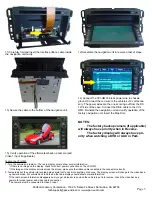
3) Remove the small Phillips screw on each side of the display. Re-
move the display from the navigation unit
Page 1


