22
WINCH DISASSEMBLY
Use the following procedure to disassemble the winch.
1.
Remove the wire rope from the winch drum and align
the drain hole in the drum with a hole in the support
side plate before removing the air hoses and mount-
ing bolts. After the winch is removed from its mount-
ing, thoroughly clean the outside surfaces. To drain
the oil, install a short piece of 1 inch pipe in the larg-
er threads of the drain hole
2.
Use a 5/16 inch Allen wrench to remove the drain
plug through the pipe and drain the oil from the winch.
3.
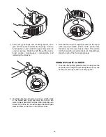
Begin disassembly by standing the winch on the
bearing support end. Place a 2x4 under the side
plate on the bearing support end to keep the winch
level.
4. Remove the air hoses that connect the air motor to
the brake cylinder. Remove the manual air valve from
the motor by removing the 4 bolts.
5.
Remove the capscrews (34) securing the motor to the
motor adapter (212). Lift the motor off the winch
using both an eye-bolt and a 1 ½ x 11 ½ pipe fitting in
the motor exhaust port (ensure full engagement of
pipe threads), or remove two bolts from the motor and
replace with eye-bolts.
6.
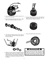
Remove the input shaft (214). Remove the retaining
ring (208), and then the bearing carrier (231) and
overrunning clutch assembly (100).
7.
The force of the brake springs is applied to the motor
adapter, so the bolts (220) must be loosened 1 turn at
a time alternating across until the springs are no
longer compressed. Remove the motor adapter
(212).
8.
Remove the brake internal parts – piston (211), fric-
tion discs (204), brake plates (205), pressure plate
(202), pins (221), springs (203), and spring spacer
(210).
9.
Remove bolts (219) which attach the brake cylinder to
the motor side plate and remove brake cylinder.
10. Remove bolts which attach the motor side plate (19)
to the base angles and remove the motor side plate.
Slowly remove the drum closure (12) using ½ - 13
eyebolts in tapped holes.
11. Remove the primary sun gear (7) and the thrust
washer (34). Remove the first planet carrier assem-
bly (300) and thrust washer (5). Remove the second
sun gear (8). Remove the second planet carrier
assembly (300) and thrust washer (5).
12. Remove the output sun gear (6). Remove the ring
gear (13) and then the output carrier assembly (400).
See procedure on p.xxx for planet carrier disassem-
bly.
13. Remove the cable guard. If the winch has a band
brake, disconnect the band brake from its operating
linkage. Slowly lift the cable drum (2) from the bear-
ing support using the clamps shown
14. Set the base angles on the ground so the bearing
support can be removed. Remove capscrews (22)
and slide the bearing support (1) out of the support
end side plate (20).
15. Remove the support end side plate (20) from the
base angles.
Refer to Sub-Assembly procedures for further disassem-
bly.
The winch and motor can weigh up to 2000 lbs.
depending on the winch model. Ensure lifting equip-
ment and overhead hoist are rated for the winch
weight and are in good working condition. Improper
rigging or hoist capacity may result in death or person-
al injury.
Do not disassemble the winch in the mounted horizon-
tal position. The winch must be standing on the support
end for disassembly to ensure thrust washer, item 34
on the drawing, remains in place. If retaining ring, item
208, is removed with the winch in the mounted hori-
zontal position, the thrust washer may fall out of posi-
tion. If this occurs, the brake cylinder must be removed
to reinstall the thrust washer.
CAUTION
Summary of Contents for BRADEN BA5A
Page 2: ......
Page 25: ...23 THIS PAGE INTENTIONALLY LEFT BLANK...
Page 26: ...24 WINCH CROSS SECTION...

