This is a convenient time to add the five pints (2.4 liters)
of recommended gear oil to the winch gear cavity. Refer
to the "Recommended Lubricant" chart for more infor-
mation.
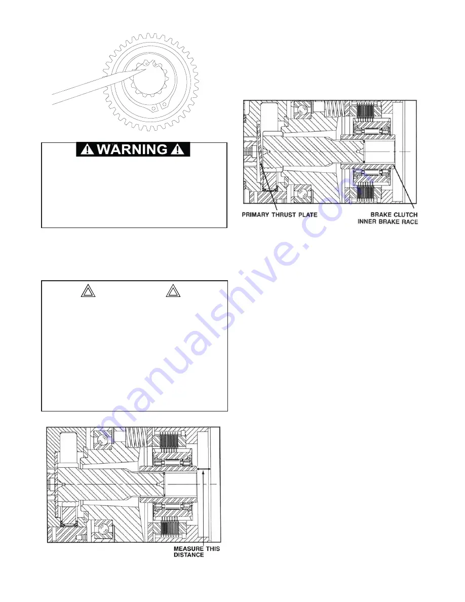
Measure the distance from the motor mounting surface
to the inner brake race. With all components properly
installed, this distance should be 11/16 in. (17.5 mm) to
3/4 in. (19.1 mm). If this distance is less than 9/16 in.
(14.3 mm), the primary spacer may be positioned as
shown below and should be checked.
The primary thrust plate is shown wedged between the
planet gears and the planet carrier. Note that the pri-
mary sun gear and the entire brake clutch assembly
have moved to the right (toward the hydraulic motor).
11. Install a new o-ring onto the motor pilot. Lubricate
the pilot o-ring and install the motor onto the motor
adapter. Evenly tighten the capscrews to 110 lb.-ft.
(149 N-m) torque.
12. Install the hoses that connect the brake valve and
motor to the brake cylinder. After the winch assem-
bly is complete, check all fasteners and fittings for
proper torque.
Care must be taken to assure the primary thrust
plate remains properly located in its counterbore
when the motor is installed for the first time, or is
being reinstalled on the winch. It is possible for the
primary thrust plate to drop out of its counterbore and
become wedged between the planet gears and the
planet carrier. If the winch is operated with the pri-
mary thrust plate wedged between primary gears
and the planet carrier, or with a thrust washer out of
position, severe damage to internal winch compo-
nents could result.
CAUTION
25
Be certain the snap ring is seated in the groove in
the splined bore of the inner race. This snap ring will
keep the brake clutch assembly correctly positioned
in the center of the friction brake pack. Binding of the
brake or brake failure may occur if this snap ring is
omitted. Brake failure may result in loss of load con-
trol, property damage, injury or death.


