5
The static brake is released by the brake valve pilot
pressure at a pressure lower than that required to open
the pilot operated spool valve. This sequence assures
that dynamic braking takes place in the brake valve and
that little, if any, heat is absorbed by the friction brake.
The friction brake is a load holding brake only and has
nothing to do with dynamic braking or rate of descent of
a load.
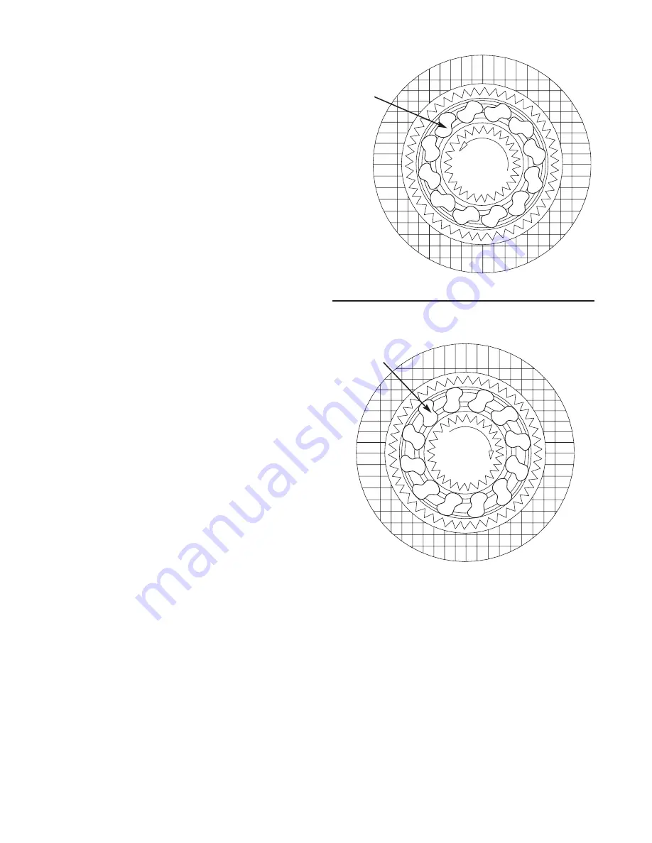
The brake clutch is splined to the primary sun gear shaft
between the motor and the primary sun gear. It will
allow this shaft to turn freely in the direction to raise a
load and lock up to force the brake discs to turn with the
shaft in the direction to lower a load. Figures 5 and 6.
The hydraulic cylinder, when pressurized, will release
the spring pressure on the brake discs, allowing the
brake discs to turn freely.
D
UAL
B
RAKE
S
YSTEM
– O
PERATION
When hoisting a load, the brake clutch which connects
the motor shaft to the primary sun gear, allows free rota-
tion. The sprag cams lay over and permit the inner race
to turn free of the outer race. Figure 5. The friction brake
remains fully engaged. The winch, in raising a load, is
not affected by any braking action. Figure 2.
When the lifting operation is stopped, the load attempts
to turn the primary sun gear in the opposite direction.
This reversed input causes the sprag cams to instantly
roll upward and firmly lock the shaft to the fully engaged
friction brake. Figure 6.
When the winch is powered in reverse, to lower the
load, the motor cannot rotate until sufficient pilot pres-
sure is present to open the brake valve. Figures 3 & 4.
The friction brake within the winch will completely
release at a pressure lower than that required to open
the brake valve. The extent to which the brake valve
opens will determine the amount of oil that can flow
through it and the speed at which the load will be low-
ered. Increasing the flow of oil to the winch motor will
cause the pressure to rise and the opening in the brake
valve to enlarge, speeding up the descent of the load.
Decreasing this flow causes the pressure to lower and
the opening in the brake valve to decrease thus slowing
the descent of the load.
When the control valve is shifted to neutral, the pres-
sure will drop and the brake valve will close, stopping
the load. The friction brake will engage and hold the
load after the brake valve has closed.
The friction brake receives very little wear in the lower-
ing operation. All of the heat generated by the lowering
and stopping of a load is absorbed by the hydraulic oil
where it can be readily dissipated.
Figure 5
Static Friction Brake Applied
Sprag
Cams
Permits free
shaft rotation
while hoisting
Hoisting
Figure 6
Static Friction Brake Applied
Load attempts to rotate shaft in opposite direction.
Brake clutch locks sun gear shaft to friction brake.
Sprag
Cams
Stopped,
Holding
Load


