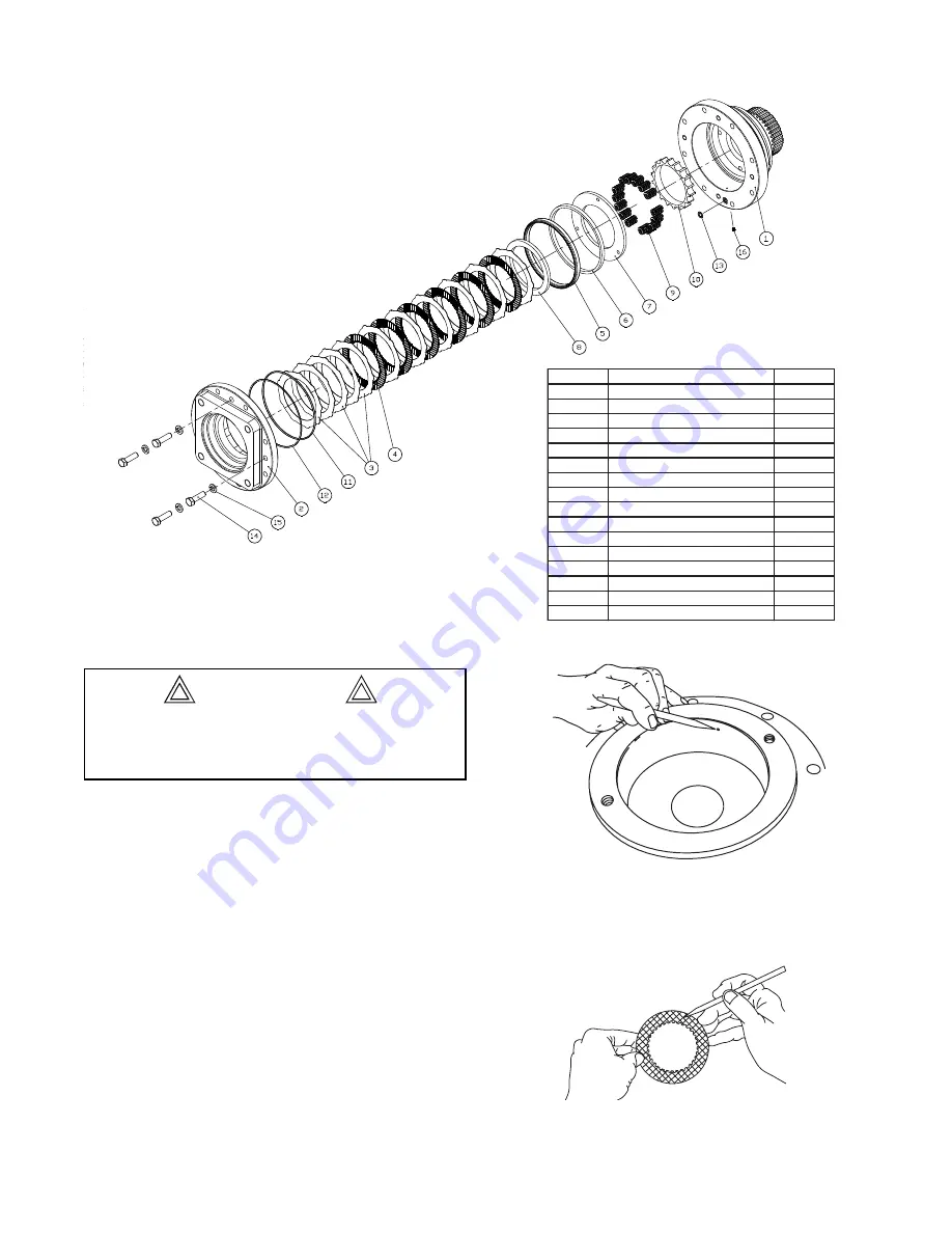
Disassembly
The brake cylinder assembly is secured to the hoist
end-plate by eight
½
-13 X 3 capscrews. The remaining
four
½
- 13 X1
¾
capscrews (14) located at 3, 6, 9, and
12 o’clock positions, hold the motor adapter (2) to the
cylinder (1) and compress the brake springs (9).
1. Place the brake cylinder assembly on a clean work
surface with the splined end down. Evenly remove
the four capscrews (14) and washers (15). Use a
cross pattern when loosening the capscrews one
turn at a time until the spring tension is released.
2. Remove the motor adapter (2) and lift out the brake
discs (3 & 4) and the spacer (8).
3. Remove the o-ring and back-up ring (11,12) from the
motor adapter. Remove the seal (5) from the cylin-
der (1). Remove the steel piston back-up ring (6)
from the cylinder.
4. Remove the pressure plate (7) and the springs (9)
and spring spacer (10).
Clean and Inspect
1. Thoroughly clean all the brake cylinder parts at this
time. Check sealing surfaces on both the cylinder
and the motor adapter. Be sure the brake release
port is clean.
2. Place the friction discs (4) on a flat surface and
check for distortion with a straight edge. The friction
BRAKE CYLINDER SERVICE
The motor adapter is under spring tension from the
brake springs. Loosen each of the capscrews one
turn at a time until spring tension is released.
Item
Description
Quantitiy
1
Brake Cylinder Housing
1
2
Motor Adapter
1
3
Steel Separator Discs
11
4
Friction Discs
6
5
Piston Seal
1
6
Piston Back-up Ring
1
7
Pressure Plate
1
8
Brake Plate Spacer
1
9
Brake Spring
15
10
Spring Spacer
1
11
O'ring
1
12
Back-up Ring
1
13
O'ring
1
14
Capscrew
4
15
Lockwasher
4
16
Expansion Plug
1
24
CAUTION


