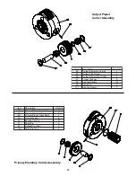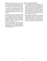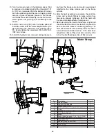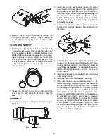
material must appear even across the entire surface
with a groove pattern visible. Replace the friction
discs if the splines are worn to a point, the disc is
warped, burned or worn unevenly. The minimum
groove depth is .003 in. (.08 mm).
3. Place the steel separator discs (3) on a flat surface
and check for distortion with a straight edge.
4. Inspect the surfaces for signs of material transfer or
excessive heat. Replace the disc if distorted, heat
discolored or mechanically damaged.
5. Measure the brake spring free length. The minimum
free-length is 1 7/16 in. (36.5 mm). Inspect the
springs for any signs of cracking or fatigue. If a
spring must be replaced for any reason, then ALL
the springs must be replaced to ensure even brake
application force.
Assembly
1. Place the motor adapter (2) on a clean work surface
with the motor side facing down. Apply a light coat of
hoist gear oil to the new brake piston seal (5) and
install the seal onto the adapter with the sealing lip
edge toward the motor. Install the o-ring and back-up
ring (11, 12) onto the motor adapter with the back-up
ring toward the motor. The cupped surface of the
back-up ring (12) must face toward the o-ring.
2. Install a steel brake separator disc (3) into the motor
adapter followed by a friction disc (4). Continue to
alternately install steel and friction discs until there
are 11 steel and 6 friction discs. Finish with 5 steel
discs on top.
3. Install the brake plate spacer ring (8) on top of the
last steel brake disc.
4. To check brake stack height, place pressure plate
(7) on top of brake spacer. Hold pressure plate
down firmly by hand and measure gap (in three
places) between motor adapter and pressure plate.
Average gap must measure between 0.160 in. (4
mm) maximum and 0.080 in. (2.0 mm) minimum. If
the gap exceeds the maximum limit, there may be
too many discs in the stack-up or the discs are dis-
torted. If the gap is less than the minimum, there
may be too few discs or the discs are worn beyond
their serviceable limit and should be replaced.
When the gap is within the minimum and maximum
values, remove the pressure plate and all brake
discs. Lubricate all friction discs with the same oil to
be used in the hoist. Install all brake discs and brake
plate spacer as described in steps 2 and 3.
5. Place the brake cylinder on a clean work surface
with the splined end down. Install the spring spacer
(10), then the 15 springs (9).
6. Install the pressure plate (7) into the brake cylinder.
Be careful that none of the springs fall over. Install
the steel backup ring (6). Apply petroleum jelly or an
oil soluble grease to a new O-Ring (13) and install it
in the brake cylinder.
Failure to replace brake springs as a set may result
in uneven brake application pressure and repeated
brake spring failure.
CAUTION
Measure gap between
pressure plate and
motor adapter
Always use the molded spring spacer to properly
position the springs in the brake cylinder. Failure to
install the spring spacer may allow the springs to
contact each other and become damaged. This
could result in loss of load control, property damage,
injury or death.
25


