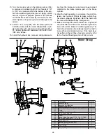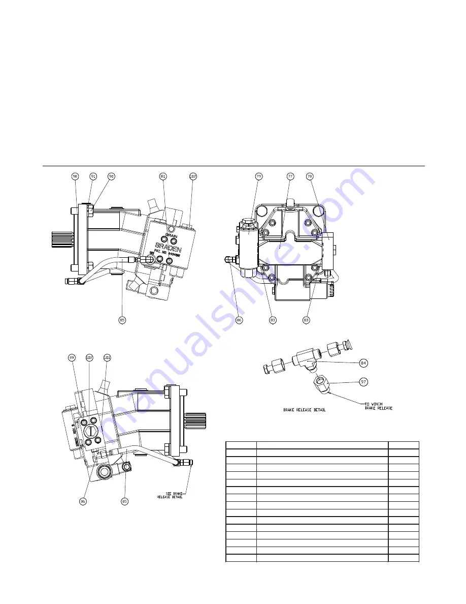
13. Turn the two jam nuts on the rotation sensor (144)
to produce an installed length of the threads of 1.21
in. (30.7 mm) measured from the bottom of the sen-
sor to the washer against the jam-nut. Apply a small
amount of general purpose grease to the threads
and install the sensor assembly into the motor end-
plate. Tighten until just snug to avoid damage to the
sensor.
14. Install a new o-ring (98) onto the motor pilot and
install the motor onto the motor adapter/brake cylin-
der assembly with capscrews and washers (90 &
91). Evenly tighten the capscrews (90) to 282 lb.-ft.
(382 N-m) torque.
15. Install the hydraulic lies, removed during disassem-
bly, from the brake valve and motor lowering port
manifold to the brake release port on the brake
cylinder.
16. After the hoist assembly is complete, check all fas-
teners and hydraulic fittings to make certain they
have been properly tightened. Refill the hoist with
the recommended planetary hoist gear oil.
17. Before returning the hoist to full service, a light load
should be lifted and held a few feet off the ground to
be sure the static brake is functioning properly. The
hoist should also be able to slowly lower the load in
a smooth and controlled manner. If the hoist does
not perform either of these functions correctly, refer
to the Trouble Shooting section of this manual.
Motor Group
Item
Description
Quantity
77
Hydraulic Motor
1
78
Lowering Port Manifold
1
79
Braden Brake Valve
1
81
Socket Head Capscrew (7/16 - 14 x 3 Gd 8)
4
83
O-ring
2
84
T-ORFS, Brake Release Port
1
85
Hose, Brake Release
2
86
Elbow
2
89
Socket Head Capscrew (7/16 - 14 x 1
½
Gd 8)
4
90
Hex Head Capscrew (
¾
- 10 x 2 Gd 8 Z)
4
91
Lockwasher (
¾
)
4
97
Adapter, Brake Release Port
1
98
O-ring, Motor Pilot
1
101
Plug, -4 ORB
1
102
Shipping Plug
2
28


