background image

1

7

Daily

Weekly Monthly Yearly

Inspect wire rope and rigging

X

X

X

X

Inspect drum clutch and shift 
mechanism for proper engagement

X

X

X

X

Inspect for external oil leaks

X

X

X

X

Check for damaged hoses / lines

X

X

X

X

Check for loose or missing bolts,
pins, keepers, or cotter pins

X

X

X

X

Check gear oil level / refill

X

X

X

Lubricate grease fittings

X

X

X

Inspect breather fitting

X

X

X

Inspect winch mounting fasteners - 
torque as required

X

X

X

Inspect structural welds

X

X

X

Check hydraulic relief valve setting

X

X

Inspect hydraulic filters / strainers

X

X

Replace gear oil

See Notes

 (1) and (2)

X

NOTES:

(1) Change the gear oil after the first 100 hours or 30 days of use,
      whichever occurs first.

Inspection Interval

Inspection Performed

(2) For winch operation in excess of 50 hours per week, oil changes should 
      occur every 6 months instead of yearly.

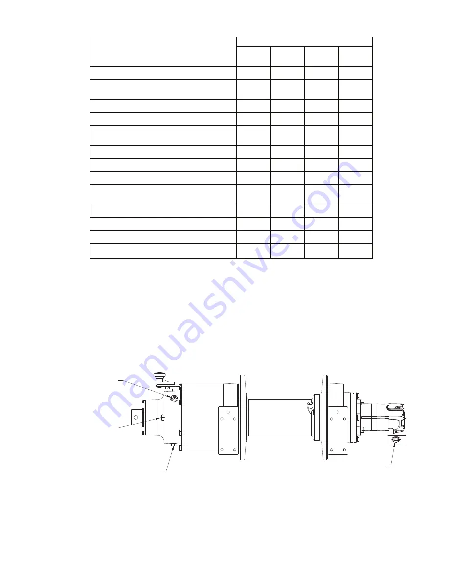
OIL DRAIN 
        PLUG

    OIL FILL
AND VENT

REEL OUT
        PORT

       OIL LEVEL
SIGHT GAUGE

Summary of Contents for Braden PD35A

Page 1: ...LIT2475 R3 Nov 2014 Printed in U S A For serial number location see page 3...

Page 2: ...DED BOLT TORQUE 23 PD35A COMPONENT EXPLOSION 24 PD35 COMPONENT PARTS KEY 25 WINCH DISASSEMBLY 26 WINCH ASSEMBLY 27 PLANET CARRIER SERVICE 29 BRAKE CYLINDER SERVICE 32 HYDRAULIC MOTOR 35 CHANGING DIREC...

Page 3: ...e PACCAR Winch Division Product Support Department at 918 251 8511 Monday Friday 0 8 00 163 0 hours CST by fax at 918 259 1575 or via the internet at www paccarwinch com Provide the complete winch mod...

Page 4: ...ALWAYS apply the parking brakes before dismounting a vehicle 7 Inspect the winch and rigging at the beginning of each work shift Defects should be corrected immediately DO NOT operate a defective win...

Page 5: ...installed in such a location that the operator is re9 moved from the electrical path to ground if the load rigging or wire rope comes into contact with or within proximity to an electrically energize...

Page 6: ...d routed to the motor at the same time Oil ow out of the motor is initially blocked by the active counterx balance cartridge As hydraulic oil pressure increases the static brake releases At this time...

Page 7: ...lower than the minimum expected temperature Under continuous operating conditions the temperature of the oil at any point in the system should not exceed 180 F 82 C 120 140 F 49 60 C is generally cons...

Page 8: ...ing hood ensure the hood opens fully and clears the bumper BEFORE welding the bumper to the mounting brackets 8 After the bumper is properly mounted to the vehicle frame connect the hydraulic lines t...

Page 9: ...sult in changes to the circuits de ned If there any questions regarding the hydraulic circuit refer to the information supplied by the original equipment manufacturer or contact the PACCAR Winch Divis...

Page 10: ...l free and result in sudden loss of load control and cause property damage injury or death A minimum of ve 5 wraps of wire rope must be left on the drum barrel to achieve rated load INSTALLATION OF SE...

Page 11: ...and that the load does not shift which may require reposi tioning the wire rope or the vehicle Once the load is positioned properly move the lever back to neutral to stop the winch Secure the load as...

Page 12: ...in neutral and the parking brake must be set 2 Move the control lever fully into the Drum Disengage position If the control lever has any resistance to shift the cable drum may be MANUALLY rotated in...

Page 13: ...e is available through all Braden dealers Have your dealer order part number 100600 It is a self adhesive weather resistant vinyl label that we recommend be installed near the winch controls of all Br...

Page 14: ...orn lock pocket may prevent the capstan from locking securely to the shaft which could allow the capstan to come off the shaft and cause a sudden loss of load control which may result in property dama...

Page 15: ...ely attach the snatch block to the anchor point folg lowing the block manufacturer s recommendations Tree Protector If the wire rope or a snatch block must be anchored to a tree or other structure for...

Page 16: ...cate the grease ttings on the bearing leg cable drum ends and clutch On some winches you will have to disengage the clutch to gain access to the drum bushing grease tting on the clutch end of the drum...

Page 17: ...nspect breather fitting X X X Inspect winch mounting fasteners torque as required X X X Inspect structural welds X X X Check hydraulic relief valve setting X X Inspect hydraulic filters strainers X X...

Page 18: ...Motor 2 578 PSI 178 Bar Maximum Flow Single Speed Motor 30 GPM 113 lpm Capstan Rating 7 Capstan 3 200 Lb 1 450 kg Capstan Speed 185 ft 56 4 m Winch Weight Winch Bumper 875 Lb 397 kg Add for Extension...

Page 19: ...l not reel in or reel out or will not reel in or reel out smoothly Check brake cylinder seal as fol lows A Disconnect the hose from the brake release port Connect a hand pump with accurate 0 2000 psi...

Page 20: ...acting on the brake release port 2 Friction brake will not hold due to worn or damaged brake discs The hoist will not hoist the rated load Reinforce mounting surface If necessary use shim stock to lev...

Page 21: ...ns hot Same as remedies for Trouble D 1 Thoroughly clean exterior and ush interior Fill drain to proper level Same as remedies for Trouble D2 Engine low on horsepower or R P M Tune adj ust engine Chec...

Page 22: ...ile reelingP in rated load See remedies for Trouble D2 Same as remedies for Trouble E2 Conduct operator training as reP quired 1 Relief valve lifting 2 Hydraulic oil ow to motor may be too low 3 Contr...

Page 23: ...rade 8 bolts studs and standard steel full thick and high nuts Higher or lower torques for special applications will be speci ed such as the use of spanner nuts nuts on shaft ends j am nuts and where...

Page 24: ...16 54 4 33 26 21 26 7 53 20 13 29 12 25 44 35 43 41 40 56 39 19 5 22 46 42 28 59 17 64 24 57 61 60 27 8 32 2 55 36 30 68 10 45 18 66 15 9 67 65 48 72 1 73 23 3 11 62 63 300 200 700 400 51 52 28 47 37...

Page 25: ...HER 6 12 RETAINING RING 1 37 SHIFTER FORK 1 62 BRAKE COUPLING 1 13 SPACER 1 38 SHIFTER HANDLE 1 63 RETAINING RING 1 14 BUSHING 1 39 ROLLPIN 1 64 O RING 1 15 SHAFT ADAPTER 1 40 SNAP RING 1 65 EXTERNAL...

Page 26: ...rier as sembly 13 Remove the thrust washer 33 and then the output planet carrier assembly 400 14 Remove the shifter shaft 4 and shifting collar 6 15 Remove the retaining ring 68 from the drum driver 1...

Page 27: ...wer out put plane t carrier assembly 400 in to ring gear 31 and ensure t he out put plane t carrier splines engage wi t h t he shif t ing collar 6 splines 10 Install one of t he re taining rings 26 on...

Page 28: ...the brake hub 62 and install the brake hub in the brake cylinder use a hand pump to release the force on the brake plates to align the plates if necessary 27 Install the winch motor 700 and connect t...

Page 29: ...rface irregu larities that may cause abrasions or friction The gears and shafts should be inspected for abnormal wear or pitting Replace if necessary 1 Install a bearing item 13 into a planet gear 11...

Page 30: ...ement or abnormal wear the bearing should be replaced Likewise the cage should be inspected for unusual wear or deformation particuO larly the cage bars If there is any damage that will impair the cag...

Page 31: ...amaging thrust washers when installing planet shafts 2 Carefully align the pin hole in the carrier with the hole in the planet gear shaft and drive the spirol pin 15 into place Always use NEW spirol p...

Page 32: ...visible Replace friction disc if splines are worn to a point disc is distorted friction material is burned or worn unevenly or groove depth is less than 0 003 in 0 08 mm 3 Place steel disc on at surf...

Page 33: ...ing may be depressed slightly to one side to lodge it in the brake cylinder bore and temporarily hold the pressure plate and springs in place while the brake cylinder is inverted and lowered over the...

Page 34: ...he brake coupling into the brake pack Turn the brake coupling back and forth to align the splines on all the friction discs Release the pres sure on the brake cylinder and remove the brake cou pling a...

Page 35: ...9 PORT B SAE 10 PORT ITEM NO DESCRIPTION QTY 1 HYDRAULIC MOTOR 1 2 BRAKE VALVE ASSY 1 3 CAPSCREW 3 5 ADAPTER 1 6 O RING 1 7 LOCKWASHER 2 8 CAPSCREW 1 2 13 X 1 1 2 G8 Z 2 9 SWIVEL NUT 90 ELBOW 1 10 AD...

Page 36: ...ntil suf cient pilot pressure is present to open the correct brake valve cartridge The friction brake will completely release at a pressure lower than that re quired to open the brake valve cartridge...

Page 37: ...through Friday from 08 00 to 16 30 hours CST or by fax at 1J918J259J1575 Failure to use the proper type and viscosity of planetary gear oil may contribute to intermittent brake clutch slipJ page whic...

Page 38: ...hes Hg 60 o F pounds sq in PSI X 6 895 kilopascals kPa kilopascals kPa X 0 145 pounds sq in PSI pounds sq in PSI X 0 0703 kilograms sq cm kg cm 2 kilograms sq cm kg cm2 X 14 22 pounds sq in PSI pounds...

Page 39: ...39...

Page 40: ......

Reviews: