27
PINION CARRIER
DISASSEMBLY
Proceed to Step 4 if the complete cartridge is removed
from the winch. This procedure assumes the parts will be
serviced with the winch on the tractor, but the same steps
are followed if working on a bench.
304
353
360
365
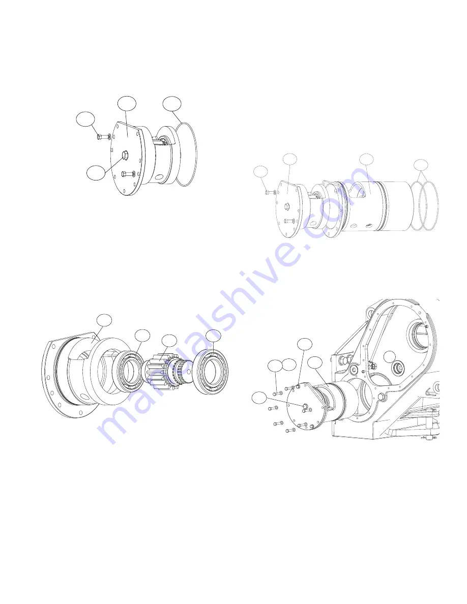
1. Remove the plug (304) and install a ¾ - 16 inch eye-
bolt in place of it.
2. Remove the bolts (353) which fasten the Pinion Carrier
Group (360) in the cartridge assembly (301). Remove
the remaining bolts (302) which fasten the cartridge
assembly to the winch case.
3. Pull on the eyebolt to remove the pinion carrier group
(360) from the cartridge assembly (301). Place the
pinion carrier group on a work bench for further disas-
sembly.
4. Use a forcing screw / cross block assembly to remove
the pinion (362) and two bearings (363) and (364)
from the bearing carrier (361).
5. Use bearing pullers to remove the bearings (363) and
(364) from the pinion (362).
6. Remove and discard o-ring (365) from bearing car-
rier.
361
362
364
363
PINION CARRIER
ASSEMBLY
1. Use an induction heater to heat the inner race of bear-
ing (364) and install on pinion (362).
2. Heat bearing (363) and install on pinion (364).
3. Use a hydraulic press to install the pinion with bear-
ings into the bearing carrier (361).
4. Install a new o-ring (365) on bearing carrier (361) and
grease lightly before installation.
5. Install the pinion and carrier group (360) in the car-
tridge assembly (310). Install the capscrews (353)
and lockwashers (354) that attach the pinion and car-
rier group to the brake cylinder (310).
6. Install capscrews (302) and lockwashers (303) which
attach the cartridge assembly (310) to the winch case
and torque. Install the plug (304) in the pinion and car-
rier group.
303
301
302
304
353
360
301
365
353


