background image

18

TROUBLE

REMEDY

PROBABLE CAUSE

G

When winch is shifted into freespool,
winch continues to operate normally.

Check pressure at freespool port.
Refer to page 6 for air and hydraulic
pressure ranges.

Replace piston O-ring seals.

Be sure there is no tension on the
wire rope when shifting to freespool.

Check winch model number and ver-
ify type of control circuit required.

1.

Insufficient pressure at the
freespool pressure port.

2.

Damaged O-ring seals in
freespool piston.

3.

There may be a load on the
drum and gear train.

4.

A winch built for hydraulic con-
trols cannot be shifted with air.

H

When winch is shifted into freespool,
red light on console does not come
on. 

Check solenoid and replace as
required.  (Terminals 30 and 87a are
connected with coil de-energized.
Terminals 30 and 87 are connected
with coil energized.  Coil is between
terminals 85 and 86)

Check bulb and replace as required.

Check switch and replace as
required. (Switch is normally open,
closed when plunger is pushed in)

1.

Faulty 

solenoid.

2.

Burned out bulb.

3.

Faulty freespool switch on
winch.

I

Winch will not remain in freespool
mode. (winch drum re-engages to
winch drive train)

1.

Leaking seals on the freespool
piston.

Replace the O-rings and backup
rings on the freespool piston.

F Continued

4.

The levelwind ratio does not
match the cable being used.

Verify levelwind ratio is correct for
the size cable being used.

Summary of Contents for Braden BP200

Page 1: ...ERGROUND PULLING WINCH INSTALLATION MAINTENANCE AND SERVICE MANUAL LIT2754 PB303 R3 November 2018 Printed in USA Copyright 2018 PACCAR Inc All rights reserved PACCAR Winch 800 East Dallas Street Broke...

Page 2: ...GEAR OIL 13 IDENTIFICATION OF MAJOR EXTERNAL WINCH COMPONENTS 14 TROUBLE SHOOTING 15 CHANGING EXTENSION SHAFT LENGTH 19 LEVEL WIND DRIVE CONVERSION 19 CHANGE FROM OVERWIND TO UNDERWIND 22 SERVICING T...

Page 3: ...illustrative purposes Continuing product improvement may cause changes in your winch which are not included in this manual Whenever a question arises regarding your BRADEN Winch or this manual please...

Page 4: ...nals to be used are thoroughly understood by everyone 11 Ground personnel should stay in view of the opera tor and clear of the winch drum Do not allow any one near a winch line under tension A safe d...

Page 5: ...INSTALLATION for control cir cuits NOTE A winch built for air control CANNOT be operat ed hydraulically or vice versa without changing the clutch spring Consult the BRADEN Service Department for deta...

Page 6: ...e frame of the vehicle When mounting the winch the method of attachment must be capable of withstanding the full 20 000 pound line pull It is important that the winch be mounted on a surface that will...

Page 7: ...pe to pull free and result in the sud den loss of load control and cause property damage personal injury or death A minimum of 3 wraps of wire rope must be left on the drum barrel to achieve rated loa...

Page 8: ...ed and no further movement is detected Applying a load on the wire rope will also help seat the wedge in the pocket Check to ensure the wedge does not protrude from either end of the pocket causing it...

Page 9: ...ION ENGAGED 1 125 FREESPOOL PORT SAE 4 ORB 7 16 20 THD 35 52 902 22 53 572 17 66 449 14 96 380 12 98 330 29 00 737 11 87 302 16 87 429 11 38 289 22 76 578 DISENGAGED WHEN HANDLE Internal brake effecti...

Page 10: ...2 83 326 9 00 229 7 58 193 23 93 608 8 01 203 19 77 502 B A 5 00 127 22 75 578 12 75 324 6 20 157 30 51 775 43 00 1 090 Approximate weights 1 735 LBS 787 kg Without Extension Shaft 1 800 LBS 816 kg Wi...

Page 11: ...t exceed 5o If the fleet angle exceeds 5o the cable will not spool correctly resulting in damaged cable and prema turely worn winch components Disengage the drum clutch and apply the drum drag brake t...

Page 12: ...at the capstan load line and hand line are perpendicular to the center of the capstan barrel Do not allow rope to pull against the flange of the capstan as rope may get damaged or may jump over the fl...

Page 13: ...LGI 2 or better Inspect and retighten as required all winch mounting fasteners Inspect and repair as required all winch mounting brackets and welds Wipe off any accumulated dust and apply a light coat...

Page 14: ...to reliable and safe operation of the winch brake and obtaining long gear train life For simplicity BRADEN has listed one 1 readily avail able product in each temperature range which has been tested...

Page 15: ...linders 2 4 Diamond Screw Handwheel 5 Diamond Screw 6 Level Wind Roller Assembly 7 Chain Case Drain Plug 8 Oil Level Sight Glass 9 Diamond Screw Disconnect Lever 10 Vent Plug 11 Cable Anchor Pocket 12...

Page 16: ...ake cylin der should be disassembled for inspection of the sealing sur faces and replacement of the seals Refer to Motor Support Brake Cylinder Service 1 The friction brake may not be releasing as a r...

Page 17: ...rated load and cause heat 2 System relief valve may be set too low Relief valve needs adjustment or repair The winch will not pull the rated load D B Apply a stall pull load on the winch while monitor...

Page 18: ...ts The winch runs hot E F The wire rope does not spool smoothly on the drum Consult wire rope manufacturer for recommendation of wire rope that best suits your appli cation Replace wire rope and condu...

Page 19: ...When winch is shifted into freespool red light on console does not come on Check solenoid and replace as required Terminals 30 and 87a are connected with coil de energized Terminals 30 and 87 are conn...

Page 20: ...isengaged from the coupling during this procedure resulting in personal injury If neces sary provide support for the torque tube and exten sion shaft as it is slid outward CAUTION The capscrews used i...

Page 21: ...ove the extension shaft and torque tube from the winch Remove the two 2 socket head capscrews from the bearing seal carrier and remove the carrier from the winch Remove the freespool spring The shaft...

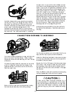
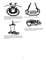
Page 22: ...e cover Be sure the thrust washer is in place on the freespool pull tube Pull Tube Thrust Washer Primary Sprocket Chain Case Cover Apply a light coat of winch oil to the outside of the freespool pisto...

Page 23: ...the cable drum or extension shaft rotates in relation to control lever movement they may have to be modified according ly CAUTION Install the diamond screw disconnect lever assembly into the cover Be...

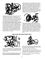
Page 24: ...the retaining ring from the carrier Remove the grease fitting and spacer the thrust wash er and the pawl Thoroughly clean and dry the bore in the carrier Apply a light coat of grease to the new pawl a...

Page 25: ...for signs of oil leakage and or physical dam age Replace the cylinder if required Install a new brake disc onto the cylinder rod Check the surface of the drum flange that the brake disc rubs against t...

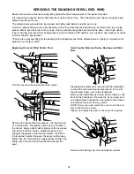
Page 26: ...nd support bracket Be sure to provide clearance for the diamond screw and other parts extending beyond the end of the support bracket Remove the brake cylinder nipple and the seven 7 cap screws and lo...

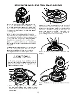
Page 27: ...chain Lift the closure out of the drum Remove and discard the O ring and the seal Inspect the bearing for wear If replacement is necessary use a bearing driver to remove the bearing 15 Lift out the ri...

Page 28: ...carrier extension from the drum If the chain case and freespool cylinder have previously been removed lift the freespool gear and pull tube assembly out of the drum Lift the drum off the chain case e...

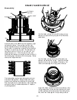
Page 29: ...springs and spring guide will come out of the brake together Closely inspect the spring guide for any damage that might prevent the springs from moving freely in an axial direction Also inspect the s...

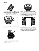
Page 30: ...rings installed correct ly The backup rings must be to the outside of the O rings Backup Ring Backup Ring O ring Next place the backup plate over the spring guide so that it rests on the top spring Th...

Page 31: ...nd place the brake piston plate over the brake piston Install the spiral retaining ring in the groove in the brake piston Pressure check the brake cylinder assembly by connect ing a hand pump with an...

Page 32: ...rol pins out of the planet gear shafts The same surface and material conditions that are detrimental to the life of the bearings and thrust washers also apply to the contact areas on the shafts and ca...

Page 33: ...s and gear Align the hole in the shaft with the one in the carrier and install a spirol pin Always use new spirol pins when assembling these carriers Drive a spirol pin into place Note that it is slig...

Page 34: ...blocks to level and raise the bracket approximately 4 to 6 inches since the end of the drum and the pull tube will extend approximately 1 1 2 inches past the bracket when installed The drum bear ing r...

Page 35: ...ar adapter The needle thrust bearing goes between the two races Install the ring gear adapter hub end up meshing the adapter with the ring gear Install the primary sun gear meshing its teeth with the...

Page 36: ...ter of the friction brake pack Binding of the brake or brake failure may occur if this snap ring is omitted CAUTION WARNING Before installing the brake discs and friction discs check their condition B...

Page 37: ...new gasket and install the motor onto the motor adapter If the slide bars were removed install them using two new roll pins Install the diamond screw into its bearing in the chain case suport bracket...

Page 38: ...arts 8 5L After the winch is installed be sure the drum rotates in the correct direction to pay out and haul in cable as indi cated at the operators station Be sure the freespool mechanism and the ind...

Page 39: ...ylinder 1 3 Brake Piston 1 4 Brake Piston Plate 1 5 Backup Plate 1 6 Belleville Spring 8 7 Spring Guide 1 8 Retaining Ring 1 9 Retaining Ring 1 10 Retaining Ring 1 11 O Ring 1 DRUM AND INTERNAL GEARS...

Page 40: ...Ring 1 100 Thrust Washer 0 09 in 1 101 Thrust Bearing 1 102 Thrust Washer 0 06 in 1 106 Lockwasher 1 2 35 107 Capscrew SPECIAL 8 108 Capscrew SPECIAL 8 113 Thrust Washer 1 114 Pipe Nipple 1 These cap...

Page 41: ...ket 1 151 Bushing 6 152 Fixed Roller Shaft 1 153 Fixed Roller 1 154 Horizontal Roller Shaft 2 155 Horizontal Roller 2 156 Retaining Ring 8 157 Moving Roller 1 158 Moving Roller Shaft 1 159 Bushing 2 1...

Page 42: ...16 NC X 7 8 G5 6 91 Chain Case Cover 1 96 Sealing Washer 1 97 Capscrew 3 8 NC X 1 G8 27 104 Capscrew 1 2 NC X 1 1 4 G5 1 124 Lockwasher 3 8 27 125 Capscrew 3 8 NC X 1 G8 2 DIAMOND SCREW DRIVE FREESPOO...

Page 43: ...ive Chain 1 230 226 225 228 227 229 233 231 232 241 240 236 234 235 238 227 239 APPLY BEARING GREASE BEFORE ASSEMBLING 251 250 253 252 254 256 255 257 Item Description Qty 225 Retaining Ring 1 226 Cam...

Page 44: ...on the Drawing MOTOR ASSEMBLY 266 265 267 268 Item Description Qty 265 Drag Brake Pad 2 266 Spacer 2 267 Spring Pin 2 268 Cylinder 2 Capscrew 3 8 NC X 1 3 4 G5 8 Lockwasher 3 8 8 DRAG BRAKE N S Descr...

Page 45: ...y Lubed Dry Lubed Dry Lubed Dry Lubed Torque LB FT Grade 5 Grade 8 1 4 20 28 5 16 3 8 18 24 16 24 7 16 1 2 9 16 5 8 8 6 12 9 17 13 24 18 45 35 70 50 23 31 50 35 80 110 80 150 110 110 55 75 150 115 210...

Page 46: ......

Page 47: ...g 60o F pounds sq in PSI X 6 895 kilopascals kPa kilopascals kPa X 0 145 pounds sq in PSI pounds sq in PSI X 0 0703 kilograms sq cm kg cm2 kilograms sq cm kg cm2 X 14 22 pounds sq in PSI pounds sq in...

Page 48: ...Copyright 2018 PACCAR Inc All rights reserved LIT2754 PB303 R3 November 2018 Printed in USA PACCAR Winch 800 East Dallas Street Broken Arrow OK 74012 www paccarwinch com...

Reviews: