2
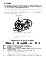
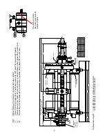
BP200 B - 23 212/106 - 1/2 - 46 H
EXPLANATION OF MODEL NUMBER
MODEL NUMBER
AND
SERIAL NUMBER
MODEL NUMBER AND SERIAL NUMBER
When information on a winch is needed, always
refer to the model number and serial number. Both
are located on the top of the motor side end plate
as indicated above.
FOREWORD
The following service instructions have been prepared to provide assembly, disassembly and maintenance infor-
mation for the BRADEN Model BP200 series winch. It is suggested that before doing any work on these units,
all assembly and disassembly instructions should be read and understood.
Some pictures in this manual may show details or attachments that are different from your winch. Also, some
components may have been removed for illustrative purposes.
Continuing product improvement may cause changes in your winch, which are not included in this manual.
Whenever a question arises regarding your BRADEN Winch or this manual, please contact BRADEN Service
Department for the latest available information.
BP200
DESIGNATES MODEL BP200 (20,000 LBS FIRST LAYER LINE PULL)
B
DESIGNATES THE MODEL SERIES RELATING TO DESIGN CHANGES
23
DESIGNATES TOTAL GEAR REDUCTION
212/106
DESIGNATES HYDRAULIC MOTOR DISPLACEMENT IN CU IN./REV (212/106 = 2 SPEED MOTOR
21.2/10.6 CU IN./REV)
1/2
DESIGNATES THE INITIAL LEVEL WIND SETTING (1/2 = 0.5 INCH WIRE ROPE)
(AVAILABLE SIZES ARE 7/16 IN., 1/2 IN., AND 9/16 IN.)
46
DESIGNATES EXTENSION SHAFT LENGTH (CENTERLINE OF DRUM TO END OF SHAFT)
(00 = NO EXTENSION SHAFT)
(AVAILABLE LENGTHS ARE 46 IN., 47 IN., AND 50 IN.)
(EXTENSION SHAFT LENGTH CAN BE INCREASED BY 2 INCHES IN THE FIELD)
H
DESIGNATES HYDRAULIC CLUTCH AND DRAG BRAKE CONTROLS (BLANK = AIR [STANDARD])
Summary of Contents for Braden BP200
Page 46: ......


