background image

2

Table of Contents

Foreword ..................................................................................................................... 2
Model Identification ..................................................................................................... 3
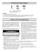
Explanation of Model Number ..................................................................................... 4
General Safety Recommendations ............................................................................. 4
Theory of Operation .................................................................................................... 6
Preventive Maintenance ............................................................................................ 10
Specifications ............................................................................................................ 11
Recommended Planetary Gear Oil ........................................................................... 12
Wire Rope Installation ............................................................................................... 13
Troubleshooting ......................................................................................................... 14
H200 Major Parts Groups Cross-section .................................................................. 19
H200 Major Parts Groups Components .................................................................... 20
Service Precautions .................................................................................................. 20
Winch Removal and Installation ................................................................................ 21
Winch Disassembly ................................................................................................... 22
Primary Planet Carrier Service .................................................................................. 28
Secondary Planet Carrier Service ............................................................................. 29
Third Planet Carrier Service ...................................................................................... 30
Output Planet Carrier Service ................................................................................... 31
Drum Clutch Assembly Service ................................................................................. 32
Brake Assembly Service ........................................................................................... 34
Brake Assembly Pressure Test ................................................................................. 35
Brake Valve Service .................................................................................................. 36
Overrunning Clutch Service ...................................................................................... 38
Cable Drum Service .................................................................................................. 39
Winch Assembly ........................................................................................................ 41
Brake Cylinder Lifting Fixture .................................................................................... 47

FOREWORD

  Managing Waste

PACCAR Winch believes in a life-cycle approach to our products. We encourage best practices regarding “Going 

Green” — making environmentally responsible decisions to “reduce, reuse, and recycle.”

•  At the end of the winch’s useful life, it is highly recommended to drain and recycle any oil remaining in the equipment.

• 

Please use a metal recycler for winch disposal to reduce landfill waste. 

The U.S. Environmental Protection Agency has developed required practices, called “management standards,” for busi-

nesses that handle used oil and metal wastes. Specific guidelines are available at the EPA and API Web sites as well 

as your state’s environmental agency Web site:  

•  https://www.epa.gov/

•  http://recycleoil.org/ 

Summary of Contents for Carco H200

Page 1: ...it our Web site at www paccarwinch com for the most comprehensive collection of winch hoist and drive information on the Internet Most publications and specification sheets are available for downloading WRITE WINCH SERIAL NUMBER BELOW First 2 numbers indicate year manufactured For serial number location see page 3 ...

Page 2: ... 35 Brake Valve Service 36 Overrunning Clutch Service 38 Cable Drum Service 39 Winch Assembly 41 Brake Cylinder Lifting Fixture 47 FOREWORD Managing Waste PACCAR Winch believes in a life cycle approach to our products We encourage best practices regarding Going Green making environmentally responsible decisions to reduce reuse and recycle At the end of the winch s useful life it is highly recommen...

Page 3: ...nels Some winches particularly those sold directly to original equipment manufacturers may differ in appearance and options NOTE The hydraulic motors and selected gear ratios on CARCO H200 winches are specifically configured for use on the intended tractor The winch may not be suitable or advisable for use on anything other than the intended tractor Contact the CARCO Service Department with questi...

Page 4: ... or attempting to jerk a load free This type of operation may cause heavy loads in excess of rated capacity which may result in a failure of the wire rope and or the winch 8 Use only GENUINE CARCO parts Do not use parts from other winch manufacturers on your CARCO winch Do not use CARCO parts on winches from other manufacturers 9 Use correct size ferrule for cable and pocket in winch drum Never us...

Page 5: ...er equipment before dismounting the tractor 14 The winches described in this manual are neither designed nor intended for use with or application to equipment used in the lifting or moving of persons 15 Install guarding to prevent personnel from getting any part of their body or clothing caught at a point where the cable is wrapped onto the drum or drawn through fairlead guide rollers 16 Keep equi...

Page 6: ...laced with a special winch section to enhance the winch performance capabilities In any case the valve section used will be a four way three position valve Typically the winch control valve is connected to the oper ator s joystick control lever by a series of hydraulic hoses Movement of the control lever directs the oil flow to the winch motor through hydraulic lines The hydraulic motor converts t...

Page 7: ...y This sequence assures that dynamic braking takes place in the brake valve and that little if any heat is absorbed by the friction discs The friction brake is a load holding brake only and has nothing to do with dynamic braking or the rate of lowering of a heavy or suspended load The overrunning brake clutch is splined to the primary sun gear shaft between the motor and the primary sun gear It wi...

Page 8: ...eadily dissipated CONTROL OPERATION BRAKE ON NEUTRAL When the winch is not in operation or when the control lever is released the handle returns to the center or BRAKE ON position by spring force Any load attached to the winch cable is held firm REEL IN Moving the control lever in the direction of tractor forward movement provides a signal to direct the oil to the winch motor to pull the cable and...

Page 9: ...e precise load control When shifted into LOW LOCK an indicator light on the main operator instrument panel will remain lit To disable LOW LOCK and return to autospeed mode press the button again The indicator light will be off WINCH LOCK OUT Winch lock out is available on some but not all CAT doz ers If your model is equipped for lock out a toggle switch located on the operator s right console adj...

Page 10: ...ntive maintenance for your CARCO winch will minimize the need for emergency ser vicing and promote long product life and trouble free ser vice The service intervals suggested in this manual will opti mize component service life The intervals may be gradu ally increased or decreased with experience of a particular lubricant and evaluation of your application GEAR CASE OIL The winch assembly should ...

Page 11: ... 3 500 PSI start of compensation Rope diameter 1 5 in 38 mm Rope storage 210 ft 64 m Drawbar Ø3 inch pin 4 5 inch opening Cable drum barrel diameter 15 in 381 mm Cable drum flange diameter 28 37 in 721 mm Cable drum barrel length 14 87 in 378 mm Bare drum rated line pull 200 000 lbs 90 718 kg Bare drum rated line speed 37 1 ft min 11 3 meters min Gear oil capacity 35 pints 17 5 qt 16 5 L Static br...

Page 12: ...e operated at low speeds raise and lower several times to prime all lines with warm hydraulic oil and to circulate gear lubricant through the planetary gear sets RECOMMENDED PLANETARY GEAR OIL Cold start up in the ambient temperature range requires extended equipment warm up to prevent erratic clutch and brake operation which may result in property damage injury or death Failure to properly warm u...

Page 13: ...erate on lower layers smaller diameter and deliver the maximum line pull Using larger cable will not always increase strength as the larger cable may be more prone to bending fatigue failure than smaller wire rope Consult your wire rope sup plier for his recommendations for the wire rope and other rigging which best suits your application Winch cable anchors ferrules and ferrule pocket are NOT des...

Page 14: ...brake Close the shut off valve and let stand for five minutes If there is any loss of pressure during the five minutes the brake housing assem bly should be disassembled for inspec tion of the brake cylinder and piston sealing surfaces and replacement of the seals Refer to Brake Housing Assembly Service for more information A Disassemble the brake housing assembly to inspect the brake discs Replac...

Page 15: ... may be slipping 4 If winch was field installed check to see that the proper stack valve section was used motor spool required 5 Drum clutch discs may be worn A The pressure at the lowering port of the motor is also directed to the brake release port This pressure must drop below 50 PSI 3 4 bar when the con trols are returned to neutral BRAKE ON Trace the hydraulic circuit back to the reservoir to...

Page 16: ...ked in high speed small displacement posi tion A Check system relief pressure as fol lows Install an accurate gauge into the trac tor pump pressure port per the tractor manual Apply a stall pull load on the winch while monitoring the pressure Compare the gauge reading to the winch specifications Adjust the relief valve as required if necessary NOTE Refer to the tractor service man ual for more inf...

Page 17: ...actor low on horsepower or RPM Tune up or adjust tractor engine for opti mum performance See tractor service manual for more information Check suction line for damage Pump worn or damaged Inspect or replace pump as needed See tractor service manual for more information A Disassemble winch for inspection or replacement of worn or defective compo nents TROUBLESHOOTING If a winch exhibits any sign of...

Page 18: ...oad is slacked off the remaining coils on the drum will stay closer together and maintain an even layer If rope of incorrect lay is used the coils will spread apart each time the load is removed Then when reeling in is resumed the wire rope has a ten dency to crisscross and overlap on the drum The possible result is flattened and crushed wire rope ultimately resulting in diminished rope life 2 The...

Page 19: ...19 H200 MAJOR PARTS GROUPS CROSS SECTION Part number 88141 ...

Page 20: ...pment 4 Use only genuine CARCO winch replacement parts which may be obtained through your CARCO dealer Never reuse expendable parts such as O rings 5 Inspect all machined surfaces for excessive wear or damage before starting reassembly operations 6 Lubricate all O rings and oil seals with gear oil prior to installation 7 Use a sealing compound on the outside surfaces of oil seals If using a thread...

Page 21: ...i fications and adaptation Remove dirt paint and rust from the mounting surfaces of the winch and tractor adapters Align the winch mounting holes with the adapter mounting holes and install and tighten all fasteners to the recom mended torque Fill the hydraulic motor case through the motor case drain port with tractor hydraulic oil Attach the winch control hoses to the motor as defined in the part...

Page 22: ...uard Item 179 from the left of the winch and disconnect the drum clutch hose 6 Remove the cap screws and washers 171 172 that secure the end cover 167 to the ring gear assembly Remove the cover and inspect or replace O ring 170 Remove the thrust bearing set 159 thrust race 160 needle bearing and 161 thrust washer from around the primary planet carrier hub Remove the 20 drum clutch springs 151 7 Re...

Page 23: ...ssembly weighs approximately 620 lbs 281 kg Refer to the Drum Clutch Assembly Service section of this manual for service procedures 179 Drum clutch hose 166 600 151 159 160 161 167 168 169 63 171 172 170 The primary planet carrier assembly 600 weighs approximately 16 lbs 7 kg The secondary planet carrier assembly 700 weighs approximately 35 lbs 16 kg The third planet carrier assembly 800 weighs ap...

Page 24: ...ing gear 16 The ring gear weighs approximately 171 lbs 78 kg 14 1 2 13 threaded bolt holes are machined into the output planet carrier pins to aid in removal Remove output planet carrier assembly 900 and drum shaft 22 Refer to the Output Planet Carrier Assembly Service section of this manual for service procedures The output planet carrier assembly 900 weighs approximately 370 lbs 168 kg WINCH DIS...

Page 25: ...hole in the top center of the cover and lift with a hoist or overhead crane The motor cover weighs approximately 108 lbs 49 kg 19 Disconnect the brake release hose 150 from the long adapter on the brake housing 300 20 Support the hydraulic motor assembly 500 securely with a lifting strap and hoist Remove the cap screws and washers 167 168 that fasten the solenoid manifold valve 162 from the winch ...

Page 26: ...o that illustrated in the back of this manual may be fabri cated The fixture is fastened to the two motor mounting holes and will assist in balancing the assembly during removal and installation 24 Remove the cable drum assembly through the rear opening of the winch housing Refer to the Cable Drum Service section of this manual for specific service procedures The cable drum 102 weighs approximatel...

Page 27: ... output ring gear and the brake housing If either of these components is removed and the cable drum is not supported externally as de scribed in the text the cable drum may come loose in the housing The cable drum weighs approximately 1 000 lbs 454 kg Damage to parts or personal in jury can occur if precautions are not taken Ensure lifting equipment has adequate capacity CAUTION The horizontal rol...

Page 28: ...hrust washer contact areas must be free of serious surface irregu larities that may cause abrasion or friction The gears and planetary shafts should be inspected for abnormal wear or pitting Replace all components as required NOTE Use care in handling the carrier to prevent damag ing the hub on the gear side of the carrier because this is a bearing surface ASSEMBLY 1 Install the bearing 57 into a ...

Page 29: ...lace all com ponents as required ASSEMBLY 1 Liberally coat the bore of a planet gear 21 with a good grade of oil soluble grease 2 Support the planet gear on a thrust washer 23 With the gear centered on the thrust washer install roller bearing 24 into the bore Install the remaining thrust washer onto the planet gear 3 Carefully install the entire gear assembly including the thrust washers on the to...

Page 30: ... first inserting snap ring 42 2 For each gear replace two sets of bearing cups 21 bearing cones 70 and bearing spacer 19 Replace ment of parts is similar to replacing the primary and secondary planet assemblies 3 Replace planet gears 15 in carrier 43 4 Replace the planet pin 51 by first replacing the re taining rings 52 Insert the shafts into the planet car rier 43 while supporting the planet gear...

Page 31: ...ust washers 54 and install 21 rollers 53 at one end of the bore Applying a light coating of grease on the bore and on the rollers aids in retention during assembly Install the bearing spacer 55 and the remaining 21 rollers 53 Repeat for all five output planet gears 2 Move the gear assembly and supporting thrust washer into place in one of the planet gear openings in the carrier Carefully slide the...

Page 32: ...ally and install the piston into the ring gear housing Apply even pres sure to the piston to seat the piston seals into the ring gear and press the piston into place Be sure to seat the piston into the bottom of the ring gear bore 3 Flip the clutch housing over and install spacer ring 39 Insert clutch plates beginning with separator plate 31 and then brake plate 30 4 Install clutch hub 36 5 Place ...

Page 33: ...iston 29309 1 030 50461 Brake plate 72180 8 031 50497 Divider plate 72204 8 032 Pressure plate 29292 1 033 Retaining ring 29303 1 034 Quad ring 106885 1 035 Quad ring 106886 1 036 Clutch hub 29246 1 038 16574 0012 Sight gauge 70193 1 039 Spacer ring 100135 1 040 Plug magnetic 40161 1 041 Fill vent plug 29678 1 042 Relief valve 1 5 PSI 10074 1 ...

Page 34: ...tion 8 Check the cable drum bearing and seal surfaces on the outside of the brake housing for excessive wear or damage 9 Place each friction disc on a clean flat surface and check for any distortion using a straightedge The fric tion material should appear evenly across the entire surface with visible grooves Replace the discs if the splines are worn to a point if there is any distortion or if the...

Page 35: ...n 308 into the brake housing bore Ap ply light even pressure to the piston to seat it against the brake plate spacer 8 Insert the spring spacer 314 into piston bore Insert 16 brake springs 313 into the spring pockets created by the spacer Two openings will remain in the spacer Ensure that openings are located 180 degrees apart 9 Install the spring retainer 315 on top of the brake springs Using a p...

Page 36: ...f utmost importance when servicing hydraulic components DISASSEMBLY 1 Remove the pilot orifice Item 9 from the brake re lease BR port using a 5 32 inch Allen wrench 2 Remove the plug 19 from the drain port 3 Remove the spool spring retainer 3 and spool spring 11 Check spring free length Replace spring if less than 1 15 16 inches 49 2 mm long ITEM NO DESCRIPTION QTY 1 Valve housing NSS 1 2 Check va...

Page 37: ...ain it is open ASSEMBLY 1 Install new O rings on the plug and spring retainers 2 Install new O rings and backup rings on the spool It is important that the backup ring is on the correct side of its O ring Take care not to cut the O ring during assembly Let the spool set for 10 minutes before in stalling them in their respective bores This will allow the O ring to return to their original size afte...

Page 38: ...ASSEMBLY 1 If both bearings have been removed from the inner race install one of them now 2 Install the overrunning clutch onto the inner race Ro tate the inner race slightly to get the clutch started onto the inner race 3 Install the other bearing onto the inner race 4 The outer race should have one retaining ring installed in one end Carefully slide the inner race with bear ings and clutch into ...

Page 39: ...Use a 002 inch 05 mm feeler gauge to make certain the cup is fully seated against the drum barrel shoulder 2 Lubricate the bearing cones with winch oil and install into the bearing cup The bearing cones will be back to back with the large end of the cones in contact with each other 3 Chill the outer bearing cup as previously described and install into the drum against the bearing cones Take care d...

Page 40: ...40 CABLE DRUM SERVICE ITEM NO DESCRIPTION QTY 102 Cable drum 1 103 Bearing tapered roller set 2 105 Spacer ring 1 107 Oil seal 1 110 Bearing spherical 1 111 Oil seal 1 ...

Page 41: ...tely 600 lbs 272 kg The output ring gear 14 weighs approximately 320 lbs 145 kg Damage to parts or personal injury can occur if precautions are not taken Make certain lifting equipment has adequate capacity CAUTION The cable drum is supported in the winch housing by bearings on the output ring gear and the brake housing If either of these components is removed and the cable drum is not supported e...

Page 42: ...o the brake housing making sure to align the splines in the overrun ning clutch Position the motor so that it angles toward the tractor Tighten cap screws to 280 ft lbs 380 N m Using cap screws and washers 167 168 fasten the solenoid manifold valve 162 to the winch mounting bracket 7 Install the thrust washers 145 146 and drum shaft 22 Rotate the shaft to engage the drum splines The drum shaft 22 ...

Page 43: ...bearing Use a light coat of multipurpose grease on the thrust bearing set 16 Install the secondary planet carrier assembly 700 and then the secondary sun gear 44 Install snap ring 143 to sun gear before installation WINCH ASSEMBLY 143 44 113 116 700 46 950 800 21 16 164 165 175 The primary planet carrier assembly 600 weighs approximately 16 lbs 7 kg The secondary planet carrier assembly 700 weighs...

Page 44: ...2 Install O ring 170 to the end cover 67 and then install the end cover using cap screws and washers 171 and 172 Make certain the thrust bearings and washers remain in position until the cover is properly located Tighten cap screws to 106 ft lbs 144 N m 23 Reinstall the drum clutch hose and drum clutch hose cover 179 Install the stud 178 and use hex nut 177 under the cover as a spacer Install the ...

Page 45: ...at hardened washers The hex head capscrews are 1 1 4 inch UNC 2A Grade 8 steel zinc plated The capscrews should be inspected for correct threads per inch with a gauge or an identical size and grade nut Depending on your applica tion the length of capscrew will differ Measure the length of the capscrew to determine your application needs It is also recommended that you clean and inspect the threads...

Page 46: ...ons with no load a few times to purge air from the lines Check all fittings and connections for leaks and repair or retighten as necessary Turn the tractor engine off when testing is complete 32 Check the tractor hydraulic reservoir level and refill as needed 33 Install the motor assembly cover Tighten cap screws to 106 ft lbs 143 N m 34 Reinstall the wire rope onto the drum Refer to the Wire Rope...

Page 47: ... or piece of heavy wall pipe or tubing Attach fixture to brake cylinder at the two holes used for the hydraulic motor Use two 3 4 10 Grade 5 capscrews 1 1 4 inches long This piece can be a solid bar or piece of heavy wall pipe or tubing Attach fixture to brake cylinder at the two holes used for the hydraulic motor Use two 3 4 10 Grade 5 capscrews 1 1 4 inches long 0 5 ...

Page 48: ...48 2018 PACCAR Inc All rights reserved LIT2753 October 2018 Printe d in USA ...

Reviews: