7
THEORY OF OPERATION
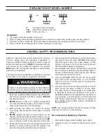
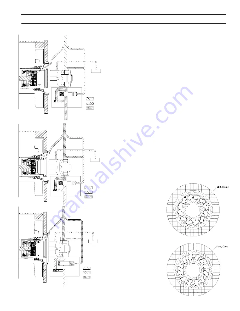
control valve is moved into the reel-out position, the spool
in the brake valve remains closed until sufficient pilot pres
-
sure is applied to the end of the spool to shift it against the
spring pressure and open a passage. After the spool valve
cracks open, the pilot pressure becomes flow dependent
and modulates the spool valve opening which controls the
reel-out speed. See Figures 2, 3, and 4.
The static brake system has three operating components:
1. Spring-applied, multiple friction disc static brake
2. Sprag-type overrunning brake clutch assembly
3. Hydraulic piston and cylinder
The static brake is released by the brake valve pilot pres-
sure at a pressure lower than that required to open the
pilot-operated spool valve in the brake valve assembly.
This sequence assures that dynamic braking takes place
in the brake valve and that little, if any, heat is absorbed by
the friction discs.
The friction brake is a load-holding brake only and has
nothing to do with dynamic braking or the rate of lowering
of a heavy or suspended load.
The overrunning brake clutch is splined to the primary sun
gear shaft between the motor and the primary sun gear. It
will allow this shaft to turn freely in the direction of reel-in,
and lock up to force the brake discs to turn with the shaft
in the direction of reel-out (Figures 5 and 6).
Figure 6.
Static fric-
tion brake applied.
Load attempts to
rotate shaft in oppo-
site direction. Brake
clutch locks sun
gear shaft to friction
brake.
Figure 5.
Static fric-
tion brake applied.
Permits free shaft ro-
tation during reel-in.
Figure 3.
Reel-out
Figure 4.
Reel-out
Low pressure
Med. pressure
High pressure
Figure 2.
Reel-in
Low pressure
Med. pressure
High pressure
Low pressure
Med. pressure
High pressure


