9
Set-Up
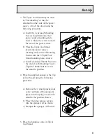
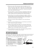
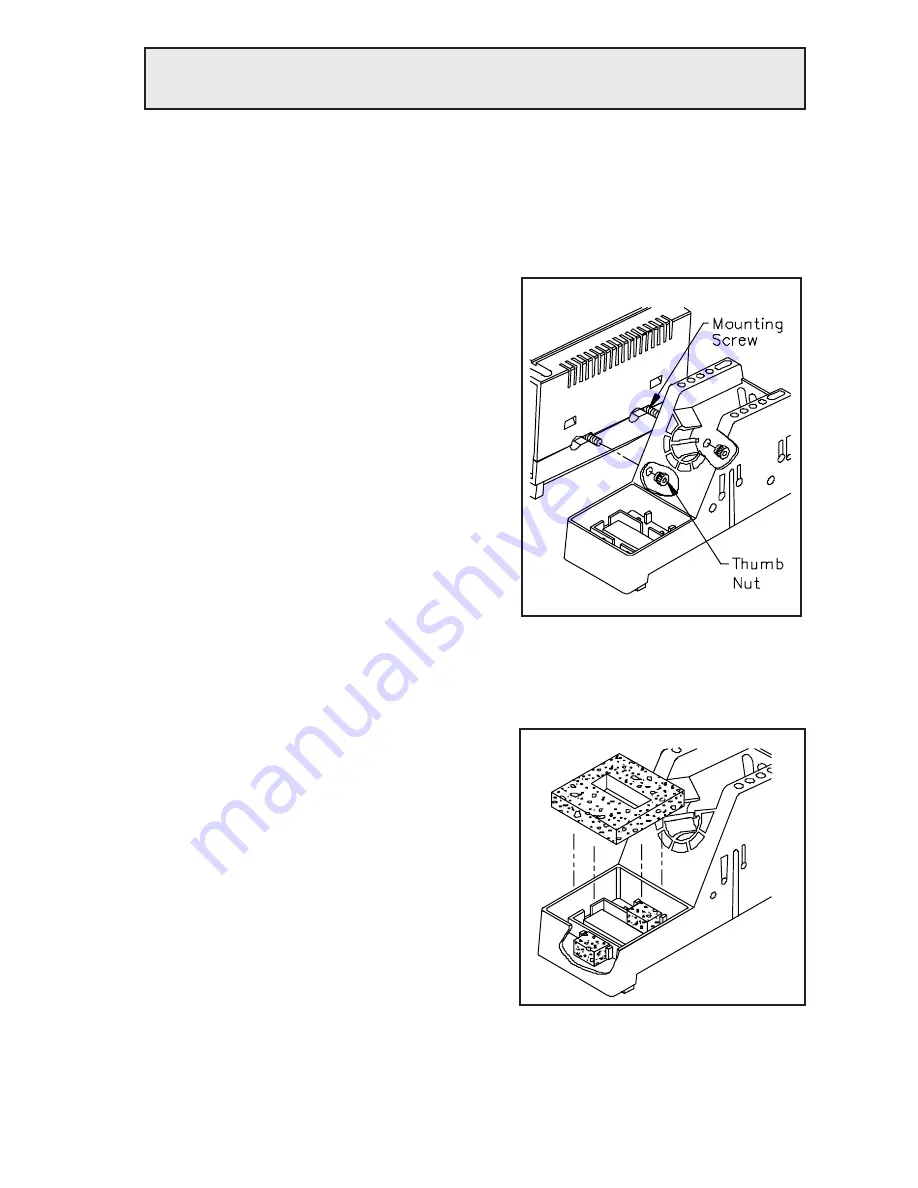
3. The Tip & Tool Stand may be used
as “free standing” or may be
attached to either side of the power
source. Attach the stand using the
following procedure.
a) Insert the 2 enclosed Mounting
Screws (head first) into the 2
power source mounting slots
shown. Slide the screws toward
the rear of the power source.
b) Place the Tip & Tool Stand
beside the power source,
inserting ends of the 2 Mounting
Screws into the 2 Tip & Tool
Stand mounting holes shown.
c) Install a knurled Thumb Nut onto
the end of each Mounting Screw.
Tighten Thumb Nuts to secure
the stand in position.
4. Place the supplied sponge in the Tip
& Tool Stand using the following
procedure.
a) Remove the 2 small punched out
center portions of the sponge &
place into the sponge well of the
stand in the position shown.
b) Place the large sponge section
into the sponge well as shown.
c) Dampen the sponges with water.
5. Place the handpiece into its Tip &
Tool Stand.
Summary of Contents for 20A
Page 1: ...Operation Maintenance Manual ST 20A Systems ...
Page 26: ...24 ...


