background image

54

Chapter 6

  Troubleshooting

Testing the bonded pair

There are no specific field installation test procedures for the bonded pair. The bonded 
pair works properly when the appropriate i3822V LEDs light. For more information, 
see “Interpreting the i3822V indicators” on page 30 and “Viewing individual DSL and 
aggregate bandwidth” on page 53 
to view the aggregate bandwidth. 

Testing the coaxial cable

Test cable continuity on coaxial interfaces. Make sure that there is not a splitter or 
bridge tap running off of the COAX home run. 

Performing an HPNA test

HPNA requires one host adapter on the network at all times; however, there can be 
multiple client adapters on the same network. Each receiver location is configured as 
a client. The HPNA host is built into the i3822V. Using a test toolkit, you can terminate 
an HPNA line into the test set and synchronize with the far-end device (for example, 
the set-top box). 

Perform an HPNA test to verify following: 

The HPNA signal and MAC address are detected on each receiver on the 

network. 

The minimum readings between each set-top box and i3822V. These 

measurements include:

Rate

Signal-to-Noise ratio 

Packet loss

Isolating HPNA issues

A failure in HPNA stations indicates that at least two devices operating over a section 
of coaxial cable have substantial signal loss between two or more HPNA devices. Use 
these tips to isolate the issue: 

Verify that all connectors are compression type and properly tighten it with a 

torque wrench at a minimum 15 in-lb, but do not exceed 20 in-lb.

Verify that all splitters have been replaced with the approved splitters.

Verify that the i3822V coaxial cable is connected on the IN port of the splitter.

Use your COAX fault locator to check for the presence of a splitter, and make sure 

that there is not a splitter or bridge tap running off of the COAX home run.

Test all cables again for excessive loss (greater than 0.5 dB per COAX run). If all 

connectors have been replaced and loss is still excessive, replace the COAX run.

Summary of Contents for HomePortal iPSU

Page 1: ...INSTALLATION GUIDE HomePortal Intelligent Gateway i3822V i38HG iPSU...

Page 2: ...herein and hereby expressly disclaims any implied warranties of merchantability or fitness for any particular purpose with regard to this manual the software or such other information in no event sha...

Page 3: ...SU Power Supply Unit 23 Installation overview 23 Preparing the installation site 24 Locating a proper site 24 Testing the electrical outlet 25 Mounting the power supply unit 25 Connecting the power ca...

Page 4: ...king i3822V LED status 52 Verifying broadband operation and statistics 52 Viewing the DSL link status 52 Viewing individual DSL and aggregate bandwidth 53 Testing cables 53 Testing VDSL 53 Testing the...

Page 5: ...fications 61 Physical specifications 61 i3822V outside unit 61 iPSU power supply unit 61 i38HG inside unit 61 Operating environment 61 i3822V outside unit 61 iPSU power supply unit 62 i38HG inside uni...

Page 6: ...as the network interface device It is installed by the service provider technician on the outside of the home The i3822V includes a broadband interface and high speed coaxial and phone line network c...

Page 7: ...on the i38HG inside unit The subscriber area is fastened with a screw that can be unfastened with any flat blade screwdriver To prevent any unauthorized access the subscriber area can be locked with...

Page 8: ...g iPSU power supply unit The Power Supply Unit iPSU supplies power to the i3822V and is installed by the service provider Unlike the i3822V the iPSU must be installed in a sheltered area either inside...

Page 9: ...y connecting computers or devices The i38HG includes an integrated wireless access point to provide wireless connectivity throughout the home or office High powered wireless technology virtually elimi...

Page 10: ...be familiar with the appropriate VDSL test tools installation practices and service verification procedures before starting this installation The following items are required for installing the i3822V...

Page 11: ...troduction 11 Test toolkit VDSL test set Mounting screws and washers for the i3822V two 10x2 1 2 hex tap screws two 10 regular flat washers two rubber washers Two SAE 10 mounting screws for the power...

Page 12: ...supply wires on page 17 Connecting the coaxial cable on page 19 Connecting the insulation displacement connectors on page 20 Securing the i3822V on page 22 WARNING To reduce the risk of fire use 24 A...

Page 13: ...x tap screws 2 10 regular flat washers 2 rubber washers Note Mount the i3822V vertically for convection cooling Allow sufficient space so the i3822V front cover can be opened for connection and testin...

Page 14: ...he home runs are on the outside of the home terminate them before connecting to the i3822V Note The bridging procedures are outside the scope of this document The VDSL area is protected with a cover t...

Page 15: ...s from entering the inside of the unit Make sure to seal any extra gaps on the cuts using the approved sealant that complies to your local requirements WARNING You must permanently connect the ground...

Page 16: ...seated in the slots along the top of the holes This prevents them from dislodging when the nut on the top of the station protector is loosened 6 Use a 3 8 hex or flat blade screwdriver to loosen one o...

Page 17: ...e securely seated 11 Repeat Step 6 through Step 10 for the second VDSL pair 12 Secure all cables and wires to the strain relief bar at the top of the grommet 13 Attach the Telco access cover that you...

Page 18: ...the wires 3 Lift up the POWER connector plastic rocker tab to expose the color coded holes on the right side of the unit 4 Insert the un stripped color coded power supply wire pair as far as it can go...

Page 19: ...n opening on the right grommet entry for the coaxial cable to fit through Note Use an appropriate tool to cut or punch through the grommet Make the cut just big enough for the cable to fit through The...

Page 20: ...on displacement connectors IDCs Each bridge module supports a separate line and can connect to up to two inside wire pairs Each IDC is connected as a separate phone line consisting of two wires Line 1...

Page 21: ...l piece and can be clamped into place Make sure that the inserted wire ends are straight and have no curls on them If the wires are bent upward or curled when inserted they will not make proper contac...

Page 22: ...1 Align the cover at a 90 angles to the unit 2 Push the cover downward toward the locking area on the left of the i3822V 3 Fasten the screw that secures the cover with the 5 32 tamper proof hex screw...

Page 23: ...onnecting the power cables on page 27 The intelligent Power Supply Unit iPSU delivers DC power to the i3822V using a single dedicated pair of 24 AWG minimum phone cable The power supply operates on 12...

Page 24: ...or level mount the iPSU above the floor level and away from any areas with a potential for standing water The life of the battery is affected by the local environment select a site that is away from e...

Page 25: ...nit Note Unless you are advised from the battery manufacturer do not install batteries measuring less than 12 75V Measure the open circuit battery voltage to make sure that it has not significantly di...

Page 26: ...gainst the wall stud 3 Mark and drill holes for the mounting screws using the template that is included iPSU package 4 Fasten the iPSU to the wall using SAE 10 or equivalent mounting screws POWER SILE...

Page 27: ...e end of the power cable from the i3822V through the round opening on the right panel of the iPSU 3 Strip 3 8 to 5 8 on the power cable pair to expose the wires 4 Connect the color coded wires that co...

Page 28: ...Power Supply Unit Connecting the iPSU to the electrical outlet Insert the AC power plug into an electrical outlet Observe the POWER indicator on the iPSU it should light red if power is present and t...

Page 29: ...the iPSU component you will do the following Starting the i3822V component on page 29 Interpreting the i3822V indicators on page 30 Enabling the ETHERNET port on page 31 Interpreting the iPSU indicato...

Page 30: ...initialization VDSL 1 and VDSL 2 These two indicators flash after 60 seconds of power application for one to two minutes and cycle three times Solid green The broadband connection is trained Flashing...

Page 31: ...x Flashing green There is inbound activity associated with the COAX port The flickering of the light is synchronized to the actual data traffic Red A device failed to be authenticated or successfully...

Page 32: ...is not receiving power from either AC or the battery Flashing red The power is provided by the backup battery or the outside unit is not yet communicating with the iPSU SILENCE ALARM Button The SILENC...

Page 33: ...it battery voltage to make sure that it has not significantly discharged before installation To connect the backup battery 1 Verify that the AC power plug is plugged into a working electrical outlet 2...

Page 34: ...g a power outage so that a phone call can be made in the event of an emergency During a temporary AC power outage the iPSU power source is switched to the battery without interruption of services When...

Page 35: ...or contact your service provider for battery replacement information To replace the battery 1 Use a Phillips screwdriver to unfasten two screws one on each side securing the power supply battery cove...

Page 36: ...g properly Note A faulty battery is indicated if the BATTERY indicator does not light green within five minutes assuming the iPSU is plugged into a functioning AC power outlet 10 Secure the battery wi...

Page 37: ...for 12 hours to turn off the low battery notification or deselect the Enable check box to disable the alert permanently 4 Click Save Enabling the alert To enable the alert 1 Open a browser and enter...

Page 38: ...SU AC power plug from the electrical outlet 2 Use a Phillips screwdriver to unfasten two screws one on each side securing the power supply unit cover 3 Loosen the battery safety strap 4 Lift the backu...

Page 39: ...connector on the battery 6 Unfasten the screw securing the power terminal cover 7 Disconnect the power supply to the i3822V 8 Loosen the mounting screws and dismount the iPSU 9 Follow the procedures o...

Page 40: ...ome networking hub that provides an 802 11b g Wi Fi access point and Ethernet switch functions for connecting personal computers and other in home networked devices to the service provider s network B...

Page 41: ...are affected by many items in households Reliability and performance are the major considerations when planning your wireless network location Avoiding interference Wireless signals are subject to in...

Page 42: ...ss signal will not be directly affected by surroundings Wireless signal strength is much stronger in an open area as opposed to an area with obstructions Keep the i38HG away from any large metal objec...

Page 43: ...re two ways to connect your computer to the i38HG through Ethernet or wireless With either connection the first computer you connect to the network is used to configure the i38HG for proper operation...

Page 44: ...card If your computer is not equipped with an internal card you can install an external wireless adapter for wireless networking The Pace wireless adapter provides a Pace Setup Wizard that automatical...

Page 45: ...HG indicators The indicators on the iPSU behave differently depending on the current state of the unit as shown in the following table Indicators Description POWER The POWER indicator turns red when t...

Page 46: ...HG will not be valid You can change your network name and wireless key by going to the user interface WIRELESS Solid green A device is associated with a specific access point Flashing green There is i...

Page 47: ...gateway 2wire net or http 172 17 0 1 as the URL 2 On the Settings tab click LAN and then click Wireless 3 Browse to the Network Name SSID text box to change the network name 4 Browse to the Wireless K...

Page 48: ...es information and instructions to do the following Checking DSL links on page 49 Checking the i3822V wiring on page 50 Checking i3822V ports on page 51 Checking i3822V LED status on page 52 Performin...

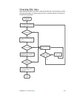
Page 49: ...roubleshooting purposes After the i3822v installation DSL connected 1 Check iNID wiring connections 2 Check iNID LEDs 1 Connect to the Telco Access Port 2 Access GUI Verify DSL signals bandwidth SNR a...

Page 50: ...ng Verify that the wiring is the same as the wiring shown in the following figure ETHERNET TELCO ACCESS FROM CO DSL LINE 1 LINE 1 LINE 2 POWER COAX DSL LINE 2 Grounding wire Telco drop wire CO Line 2...

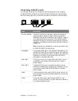
Page 51: ...T The standard IEEE 802 3 10 100 BASE T ETHERNET port is disabled by default When enabled it supports other Ethernet devices such as switches or hubs This port is used only if the subscriber has Cat 5...

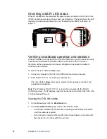
Page 52: ...a computer to the TELCO ACCESS port and open a browser 2 Enter http 172 17 0 1 on the browser address line The user interface Home page opens displaying the aggregate upstream and downstream bandwidth...

Page 53: ...ment Rate for both downstream and upstream directions Max Rate for the downstream direction Noise Margin Attenuation Output Power Note See Testing cables on page 53 if any of these readings are outsid...

Page 54: ...top box Perform an HPNA test to verify following The HPNA signal and MAC address are detected on each receiver on the network The minimum readings between each set top box and i3822V These measurement...

Page 55: ...LED indicators light up For more information about iPSU status and what the LED indicators mean see Interpreting the iPSU indicators on page 32 Verifying the backup battery operation To verify the ope...

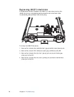
Page 56: ...ice 1 Remove the connector from both DSL line 1 grey and DSL Line 2 black ports 2 Remove the connector from both phone ports grey and black on the IDC 3 Remove the connector from the Line 1 green port...

Page 57: ...se and or packaging Do not use the adapter if the cord becomes damaged Do not attempt to service the adapter There are no serviceable parts inside Replace the unit if it is damaged or exposed to exces...

Page 58: ...r oils Keep the gateway away from direct sunlight and anything that radiates heat such as a stove or a motor Do not place the gateway in enclosed areas having restricted airflow such as electrical cab...

Page 59: ...there is no guarantee that interference will not occur in a particular installation If this equipment does cause harmful interference to radio or television reception which can be determined by turnin...

Page 60: ...ect the operation of this equipment If this happens the telephone company will provide advance notice in order for you to make the necessary modifications to maintain uninterrupted service If trouble...

Page 61: ...Physical specifications i3822V outside unit 13 0 in x 12 0 in x 5 0 in 33 0 cm x 30 5 cm x 12 7 cm 6 4 lb 2 9 kg iPSU power supply unit 6 75 in x 7 5 in x 4 5 in 17 1 cm x 19 1 cm x 11 4 cm 2 lb with...

Page 62: ...employ a separate primary protector for the equipment appropriate cabling should be run to the equipment etc WARNING For the purposes of determining placement and location of fuse links or fuse cable...

Page 63: ...56 COAX connector 20 connecting insulation displacement connectors 20 connecting network cables 15 connecting power supply wires 17 connecting the coaxial cable 19 LED indicators 30 mounting 12 mount...

Page 64: ...t connector IDC 18 LED indicators 32 LEDs BATTERY 32 POWER 32 mounting 25 POWER indicator 28 power terminal cover 27 replacing 37 N network name changing 47 O outside unit i3822V 6 P phone jack 21 POW...

Reviews: