background image

System Operations Manual, Rev B 

www.paceworldwide.com


Page 11 of 21 


NOTE:  

Read the “Programming Your System” sections of this manual to utilize the full 

capabilities of the system.   


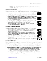
LED Display, Normal Operation 

 
The LED Display provides a 3-digit display of temperature information.  The LED Display will show: 
 

1.  A display of "888" on initial power up to ensure that all LEDs on the display are 

working.  

2.  A display of the software version of the installed microprocessor (e.g., "1-2") for 1 

second on initial power up after the "888" is displayed. 

3.  Actual tip temperature of the connected handpiece during normal operation.  The tip 

temperature displayed will flash when the system is in Temperature Setback.   

4.  The displayed temperature will decrease and stabilize at 177°C (350°F) when the 

system is in Temperature Setback. 

5.  "OFF" when the Set Tip Temperature has been set to Off (below minimum set tip 

temperature).  Refer to the "Programming Your System" portion of this manual. 

6.  "OFF" plus the LED Display will be flashing when the unit has entered Auto Off.  

Refer to the "Programming Your System" section of this manual. 

7.  Error messages ("OSE" or “CEE”) if a system fault is detected.  Refer to the 

"Corrective Maintenance" portion of this manual. 


LED Display, Temperature Adjust Mode 

 
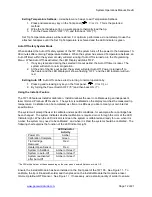
The LED Display will show the following when adjusting the desired Set Tip Temperature.  

1.  The Set Tip Temperature. 
2.  "HiL" (High Temperature Limit) when adjusting the set tip temperature and the 

maximum allowable temperature is exceeded.  Refer to the "Programming Your 
System" portion of this manual. 

3.  "OFF" (Low Temperature Limit) when adjusting the set tip temperature and the 

minimum allowable temperature is exceeded.  Refer to the "Programming Your 
System" section of this manual. 

3.  "EP" will be displayed if a Set Tip Temperature adjustment is attempted and a 

Password has been stored in system memory.  As the Password is entered, the 
display will change to the Set Tip Temperature if the entered Password matches the 
stored Password. 

5.  "no" will be displayed if the entered password does not match the stored Password. 


Temperature Setback Mode 

 
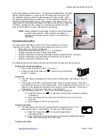
To preserve tip life and save energy, the TW 100 system can be programmed to automatically set back its 
Tip Temperature to 177°C (350°F) after a selected period of handpiece inactivity.  The LED Display will 
blink “177” or “350” depending on the selected temperature scale.  As received from the factory, this 
feature is enabled.  Refer to the “Programming Your System” section of this manual to disable or adjust 
the time-out period of this feature.  The operator can also force the system into Temperature Setback.  
 

Activating Temperature Setback:

  There are two ways to activate the Temperature Setback feature. 

1.  AUTOMATIC ACTIVATION:  The system can be programmed so that this feature will 

automatically activate after a pre-selected period (10-90 minutes) of handpiece inactivity.  
See the “Programming Your System” section for details on programming this feature. 

2.  MANUAL ACTIVATION:  The operator can manually force the system into Temperature 

Setback by performing the following procedure. 

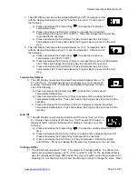
a.  Press and hold the Scroll Down (

) Key and the Scroll Up (

) Key. 

b.  Release both keys. 
 

Summary of Contents for HW 100 HeatWise

Page 1: ...HeatWise TW 100 TempWise Soldering Systems 5050 0512 Rev B PRM Voltage Part Number HW 100 HEATWISE System 115 VAC 8007 0387 HW 100 HEATWISE System 230 VAC 8007 0388 TW 100 TEMPWISE System 115 VAC 800...

Page 2: ...tion 8 Operation 9 Definitions 9 HW 100 System 9 TW 100 System 10 LED Display 11 Temperature Adjust Mode 11 Temperature Setback Mode 11 Auto Off Mode 12 Using InstaCal 12 Programming Your System 13 En...

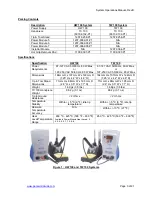
Page 3: ...Max 97 127 VAC 50 60 Hz 80 W Max or 197 253 VAC 50 60 Hz 80 W Max Dimensions 184mm H x 107mm W x 122mm D 7 25 H x 4 2 W x 4 8 D 184mm H x 107mm W x 122mm D 7 25 H x 4 2 W x 4 8 D Tip Tool Stand Dimen...

Page 4: ...sert d un produit PACE 1 Danger potentiel de choc lectrique Les proc dures de r paration sur les produits PACE doivent tre effectu es seulement par du personnel qualifi Des parties de l quipement d sa...

Page 5: ...all OSHA e agli altri Standard di Sicurezza applicabili 3 Le resistenze PACE Sensatemp e le punte installate sono calde quando la stazione accesa e per un periodo successivo allo spegnimento Non tocc...

Page 6: ...rte Est seguro de poner la herramienta en su soporte despu s del uso y permita que la herramienta enfr e antes de guardar 5 Siempre use sistemas de PACE en una rea bien ventilada Un sistema de extracc...

Page 7: ...r a workbench or shelf See Figure 5 It is important to note that the Interlock can be mounted on either side of the power source In the examples below the Tool Stand has been mounted on the left of th...

Page 8: ...extraction equipment is recommended Tip Cartridge Installation Tip cartridges are fitted with a key lock device This feature ensures that tip cartridges are held firmly in position and will maintain...

Page 9: ...hat will independently set back the Set Tip Temperature to 177 C 350 F after a user selected or preset period of handpiece inactivity HW 100 Heat Wise System The HW 100 requires the use of a Power Mod...

Page 10: ...Adjust the temperature by pressing and holding Scroll Up Key or Scroll Down key Observe the display as the Set Temperature increases first in increments of 5 then in increments of 10 When the desired...

Page 11: ...ture is exceeded Refer to the Programming Your System portion of this manual 3 OFF Low Temperature Limit when adjusting the set tip temperature and the minimum allowable temperature is exceeded Refer...

Page 12: ...d releasing any key on the front panel or or 2 By turning the Power Switch OFF 0 and then back ON l Using the InstaCal Feature The TW 100 features InstaCal calibration InstaCal allows the user to cali...

Page 13: ...time out period Enable or disable the Auto Off feature and adjust the time out period Enable or disable the Calibration mode The following instructions should be performed to familiarize the operator...

Page 14: ...wn as tens of minutes e g S 3 equals 30 minutes A display of S 0 indicates that Setback is disabled Choose one of the following a Press and release the Program Key to keep the currently stored Tempera...

Page 15: ...e OFF Temperature Setback Enabled 30 minutes Auto Off Enabled 60 minutes Cartridge Offset Zero Table 1 Factory Settings InstaCal Adjustment In most cases the InstaCal calibration will closely match yo...

Page 16: ...the up and down keys adjust the ICA offset as needed 4 Press the program key to exit the ICA menu and resume normal operation PACE does not recommend modifying the ICA offset to compensate for tip ge...

Page 17: ...0023 P1 1 8 90 Degree Chisel Extended 1124 0024 P1 1 16 30 Degree Bevel 1124 0025 P1 1 16 Conical Sharp Extended 1124 0026 P1 1 16 Chisel Bent 30 Degrees 1124 0027 P1 3 128 Conical Sharp Extended 1124...

Page 18: ...o be attached to the Power source Shown with HW 100 1335 0251 P1 Bench Mounting Bracket for HW 100 TW 100 1321 0639 P1 TC 100 Handpiece Tip cartridge not included 6010 0132 P1 Replacement TC 100 cord...

Page 19: ...ng may need to be replaced over time To replace the O ring follow the procedure below 1 Disconnect the TC 100 from the power source 2 Remove the tip cartridge 3 Unscrew the cap from the back of the TC...

Page 20: ...lusions and limitations herein apply to all persons and entities SELLER MAKES NO OTHER WARRANTY EXPRESS OR IMPLIED AND MAKES NO WARRANTY OF MERCHANTABILITY OR FITNESS FOR A PARTICULAR PURPOSE Seller w...

Page 21: ...MODULE and TEMPWISE The following are registered trademarks and or service marks of PACE Incorporated Laurel Maryland U S A ARM EVAC FLO D SODR MINIWAVE PACE SENSATEMP SNAP VAC SODRTEK SODR X TRACTOR...

Reviews: