Chapter 2
Installing the i3822V (Outside Unit)
21
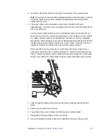
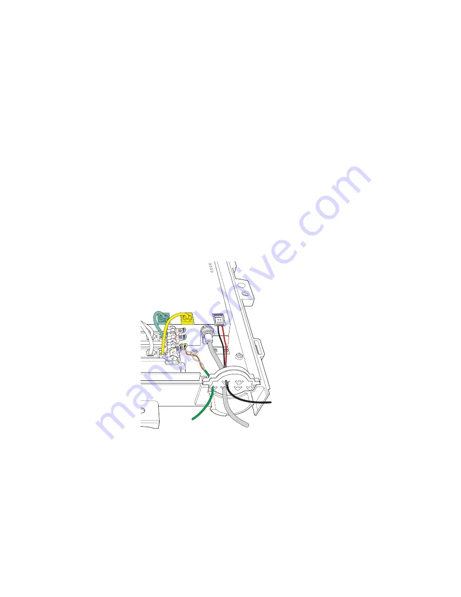
2. Insert the subscriber’s inside wire through the opening of the grommet entry.
Note:
Do not remove the protective gel-filled insulation around the holes; it acts as
a moisture barrier and prevents unwanted small particles from having direct
contact with the wires.
3. Lift up one of the color-coded plastic rocker tabs of the IDC and insert
approximately 1-1/2 inches of an un-stripped wire into each hole that matches the
wire color of the tab.
You may feel an initial resistance when inserting the wires into the tabs. Do not
stop there. If you do, the connectors might close on the insulation, but no contacts
are made. The wire needs to be inserted past that point so that it is completely
through the vertical metal piece and can be clamped into place. Make sure that the
inserted wire ends are straight and have no curls on them. If the wires are bent
upward or curled when inserted, they will not make proper contact.
If the subscriber’s wiring colors do not match these tab colors, inspect how a
phone jack inside the home is wired and attach the colored wires similarly to this
device. A typical example would be white with blue strip to green; blue with white
stripe to red; white with orange stripe to black; orange with white stripe to yellow.
4. Look through the plastic and make sure that the wire passes through the IDC
blade.
5. Press down the tab to lock the wire.
6. Tug gently at the wires to make sure that they are securely seated.
7. Repeat Step 3 through Step 6 for the second line.
8. Secure all cables and wires to the strain relief bar at the top of the grommet.
DSL LINE 2
E 1
FROM CO
LINE 1
LINE 2
COAX
LINE 2
O LINE 1
TO TEST VOICE SERVICE PLUG IN WORKING PHONE
POWER


