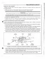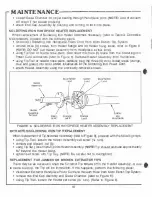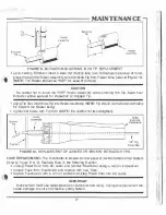
e_,
----------- OPE.RATION
SET-UP:
•
Po!:i
,
t
mn
Voltageo
Selector Switch
�o
ca
t
ed on
rear
of system) to
h ptoper
10lt.1ge
pos.ition.
�
MP
O
RT
A
N
T
\k>ltage
S
e
l
e
ct
or S
1
.vilc position musl match e
i
n
com
i
n
g supµ 'a' vc
lt
age. (�p e:
1
20
V
AC
i
n
co
m
i
ng voltage, 120V Se ector Swhch pos
1
tlon
)
.
•
:1
t1
a
ch
Extractor Handpiece Pov.·or
C
o
nn
ec
t
o
r to Output
PuM.--er
Receptacle
(J ), push and turn
to
l
o
c into place.
•
attach Solde
n
ri
g Iron Handpieca Power Connector to Outpul P01,,ver Receplac e
{J
2)
,
?USh
and
urn ,c loc!< 1 n,o place.
•
p
l
u
g ?ows
r Cord into
a.
corwenient AC oulleL
•
Sf.ii
e
m
is
now reaay for ope ra
ti
on
.
OPERAT�ON:
Fsrforrn the fc la,ving steps to become op
er
ab
l
e
, agan using Figure 2 o
r
3 or r ferenoe:
MBT-l00/100E
111
p
l
a
ce the Variable
Tem
pera
t
u
re
C
o
tr
o
l
to posit o
n
'7".
This settmg
I
s used
for
r
e
fe
re
n
ce and
he,.::ils ,hi! Ex-trac[or Handplece Tip to approxlmately 650
°
F.
•
1
f
e systam is lO be used rar
deso
l
d
e
ri
n
g on a pri
tad c1rcurt board
(
c
a
n
ta
i ing
static
se
n
.slw:e co
m
po
ne
n
t
s
)
,
connect e g
r
o
und
wire bewteen
t
h
e Eanh Ground iermmal and a com
mon ground on the PCB. Th·s wlll e
l
i
m
i
n
a
te
any electrical discharge to these components.
•
the
E):tr
a
ctor
1p should pro
t
ruce a
oo
rox
im
a
t
e
l
-y
:v."
beyond
t
h
Heater Assembly body. If Tip
1s p
ro
l
r
uding more than �·. repos1lion using the lip Toot
111
p
l
a
CJ! n
,
e
M
a
i
n
P
owe
r
Switch
lo
the
"'ON" position.
The
lndlcato
U
gh
t
should
i
l
l
u
m
i
nat
e
.
•
allow a
pp
r
oxlmate
�
y four
(4)
mlnules ror .'arm-up.
•
the system 1s now ready for desot
d
ei
rin
g
.
f
NOT
�
:
D
s
p
re-.ss
i
n
g th
Ex
tr
ac
t
or Handpiace
vacuum
C
o
n
t
r
o
l
Switch a
ct
i
v
a
t
es the vacuum mode of the
M
o
tor
l
P
u
m
p
J
.
•
a er
eomple ion cf
d
eso
l
der1n9
.
turn system otf by retumfng
t.he
Mairi Pow@r
S
w
rt
c
h
to
tre
"O
F
F'" po
s
1t
1
o
n
.
(
N
O
TE
:
lndicato
ll
g
h
l
Yill not be illummatsd).
M BT-2001200E
•
piaca lhe ½r
J
a
t
l
e Temperature Controls to posHion
'7'
This
salting
,
s
used
for re
r
e
r
en
c
e
am1
heats Lhe Ex::mctor and/or Sc darlng Iron Tip to
appr
�
1
m
at
.el
•1
65!)
°
F.
•
rf
the
sys
t
e
m is
to be used rar desoldering il!ndlor so
ld
e
r
i
ng
on
a
p-Jmed
circull board (cortain�
ing stalic sensitive
co
mpo
n
e
nt
s
}
.
c
o
nn
ec
t
a ground ·,vire batween the Earth Ground Te
r
m
i
n
a
l
and a common grourid o lhe PCB. This will e0mi ate any electrical discharge to h�se cam
porents.
•
tlits Exl
r
a
c
to
r and Sol
d
e
rin
g
Iron Tips
shou
d
protrude approximately li-1
H
beyc
nd
l
hs Heaier
iAssemtHy body. 1r Tip �
p
r
o
t
r
u
d
i
ng
m
o
r
e lhan ¾".
r
e
p
os
it
i
o
n
usmg ne T
i
p
T
oo
l
.
• place ttrc
r
ain Pc-wcr S Yrtc' to the MON· posrlion. 1e
l
nd
i
ca
�
or
Ug
h
t
should Illuminate.
•
al10YJ a
pprOlC
imat
el
y
fo
u
r
(") minutes or warm-up.
•
lhe
system Is
ow
ready
for
deso
l
de
ri
ng
a.ndlor .solde
r
i
n
g
,
(
NOTE
� Depressing the Extractor
Han
d
p
1
e
ce Vacuum Con rol Switch activates t e vacuum mode of the
M
otor/Pump
)
.
•
arter como elion or
d
esol
de
ri
ng and/or soldering
J
tum system off oy relurning
the ain
Power
Swi
t
c
h
ta .he "OF� p
o
si
t
i
o
n.
{
NOT!:
:
In
dica
t
or Light will not be
ill
u
m
i
n
a
t
e
d)
.


