GENERAL INFORMATION
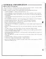
PARTS IDENTIFICATION
TABLE
2. MICRO BENCH TOP SYSTEM (MBT-200/200E) PARTS IDENTIFICATION
•
VARIABLE TEPERATURE CONTROL (J1)-provides variable temperature control for Extrac
tot Handpiece Tip temperature,
•
VARIABLE TEMPERATURE CONTROL (J2)- prov1des variable temperature control for Solder
Iron Handplece Tip temperature.
•
INDICATOR LIGHT -amber fight Indicates Main Power Switch
is
"ON".
•
MAIN POWER $WITCH-controls input power with,n Micro Bench Top System.
•
PRESSURE CONTROL-air control for hot-air jet mode.
•
VACUUM FlTIING-vacuum
now
for solder removal.
•
OUTPUT POWER RECEPTACLE (J1)-connects power from Micro Bench Top System to
Extractor Handp1ece.
•
OUTPUT POWER RECEPTACLE (J2)-conneets power from Micro Bench Top System to
rJI-..
Soldering Iron Handpiece.
\\_,
·
•
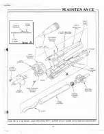
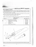
EXTRACTOR HANDPIECE-tool used for desoldering, hot wr pressure
(blind
side solder
removal) and hot-air jet mode (removes solder connections and shrinks tubmg) funcllons.
•
VISIFILTER'"-collects and prevents foreign sustances from entering the Motor/Pump
Assembly .
•
VACUUM CONTROL SWITCH-Extractor Handpiece "ON/OFF
switch activates
Motor/Pump.
•
EXTRACTOR T IP-heals
and
extraets s older from components.
•
HEATER ASSEMBLY -provides heat to Extractor Handpiece Tip.
•
CUBBY HOLOERS-convenlenlly stores Extractor and Solder Iron Handpleces.
•
CLEANING STATION-provides wire brush and sponge ior cleaning and storing Tips.
•
EARTH GROUND TERMINAL-provides a ground between Micro Bench Top System and PCB,
thus preventing an electrical charge from damaging sensitive components.
•
SOLDERING IRON HANDPIECE-tool used for soldering functions.
•
SOLDERING IRON HEATER ASSEMBLY-provides heat to Soldering
Iron
Tip.
•
AC POWER RECEPTACLE-provides AC power to Micro Bench Top System from AC
outlel
through Power Cord.
•
VOLTAGE SELECTOR SW
IT
CH-s
.
e
i
e
cts proper voltage which corresponds with Input line
voltages. (NOTE: Switch must be placed in the proper position bef0<e plugging in Power Cord).
•
POWER CORO-provides
ma,n
power from AC outlet to AC Power Receptacle.
•
LINE
FUSE (F1)-provides overload
protection for
Micro Bench Top System.
•
CIRCUIT BREAKER (CB1)-provides ovet1oad protectlon for Micro Bench Top System.
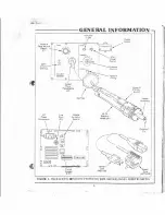
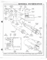
Figure 3 identHies the controls and indicators required for operation on the Micro Bench Top
System(s) (MBT-200/200E) and
the
Extractor Hand piece. Refer to Table 2 and Figure 3 for
locatfon(C
·,
and identification of each pan.
6
··---. - ··-·· ·· ··· · · ·
.....


