GENERAL INFORMATION
PARTS IDENTIFICATION
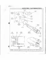
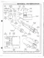
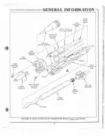
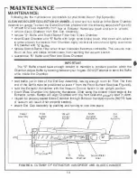
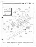
Table 3 an<l Figure 4 Identifies the parts that make-up the SX-55 Extractor Handplece. Refer
to Table 3 and Figure 4 for locat10n and Identification of each part.
TABLE
3. SX-55 EXTRACTOR HANDPIECE PARTS IDENTIFICATION
•
HEATER ASSEMBLY - supplies heal to
the
Extractor Tip.
•
HEAT OISSIPATOR-reduces
heat
transfer from the Heater Assembly to the Handpiece.
•
HEATER ASSEMBLY MOUNTING SCREWS-mounting screws for attaching Heater Assembly
to Handp1ece.
•
HEAT DISSIPATOR MOUNTING SCREWS-mounting screws for attaching Heat Dissipator
10 Handplece.
•
HEAT OISSIPATOR WASHER-spacer separating the Heat D1ssipator
from
the Handplece.
•
LOWER HANDPIECE SHELL-Iowa· section oi SX-55 Ex1ractor Handplece.
•
UPPER HANOPIECE SHELL-upper section of SX-S5 Extractor Handpiece.
�
•
RAM
P
-
aflg
n
m
e
nr guides for Glass Chamber.
�
-
-
•
CORD ANO SWITCH ASSEMBLY -supplies AC power to
the
S X -55 Extractor Handpiece from
Power Source.
•
SPACER-provides positioning oi tha Cord and Switch Assemoly within Upper Handp,ece
Shell.
•
C-CUPS-retaining cl
i
ps holding U�per and
Lower
Handpiece Shells together.
•
SWITCH ASSEMBLY MOUNTING SCREWS-
mounting
screws for attaching
Cord and
Switch
Assembly to Upper Handpiece Shell.
•
HANDPIECE MOUNTING SCREWS-mounting screws for attaching Upper and Lower Hand
piece Shells together.
•
END CAP ASSEMBLY -provides
a
,acuum line lrom the Power Source to SX-55 Extractor
Handpiece.
•
GLASS CHAMBER-coUectlcn chamber for extracted solder.
•
·s·
BAFFLE-breaks up extracted solder in Glass Chamber.
•
SX -55 EXTRACTOR FILTER-prevenls ex1rac,ed solder and/or contaminates from entering
Power Source Motor/Pump.
8


