


- 6 -
Icon Bar Explanations
The icon bar can tell us several different things at a quick glance. The icon at right shows the
internal cooling fan is operational and should always be present.
One of the following three icons will also always be present in the top right corner.
Indicates the internal sensor is currently active.
The Bottom Sensor is active when this icon is displayed.
Indicates the Top Sensor is active.
This icon only shows up when the power limiter has been activated, and designates the unit as
currently operating at half its normal capacity, 800 watts. If this icon is not present, the unit can
make use of the entire 1600 watt capacity.
Finally, if the screen is locked using the password feature a lock
will appear in the icon bar area.
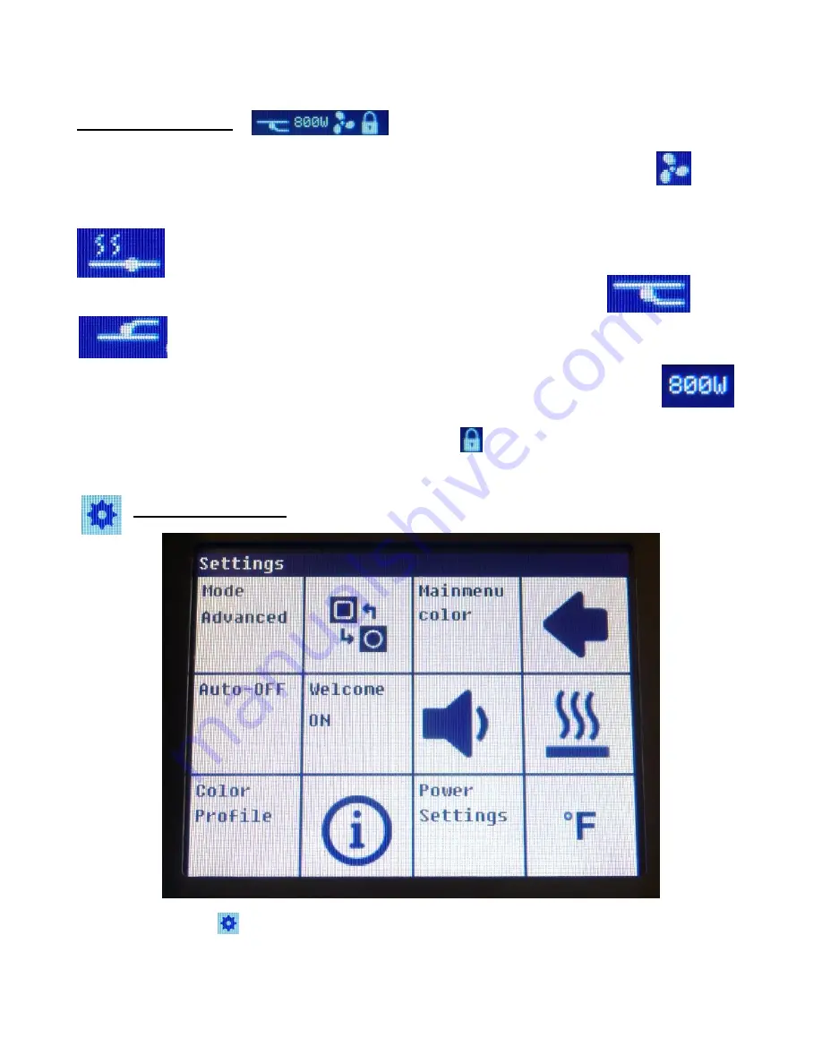
Device Settings Menu
Selecting the gear icon
brings up this screen. Tap the arrow in the upper right hand corner to return to the
main menu.


